Arduino Mega and ESP32 Powered Robotic Controller with Distance Sensing and Line Tracking
Circuit Documentation
Summary
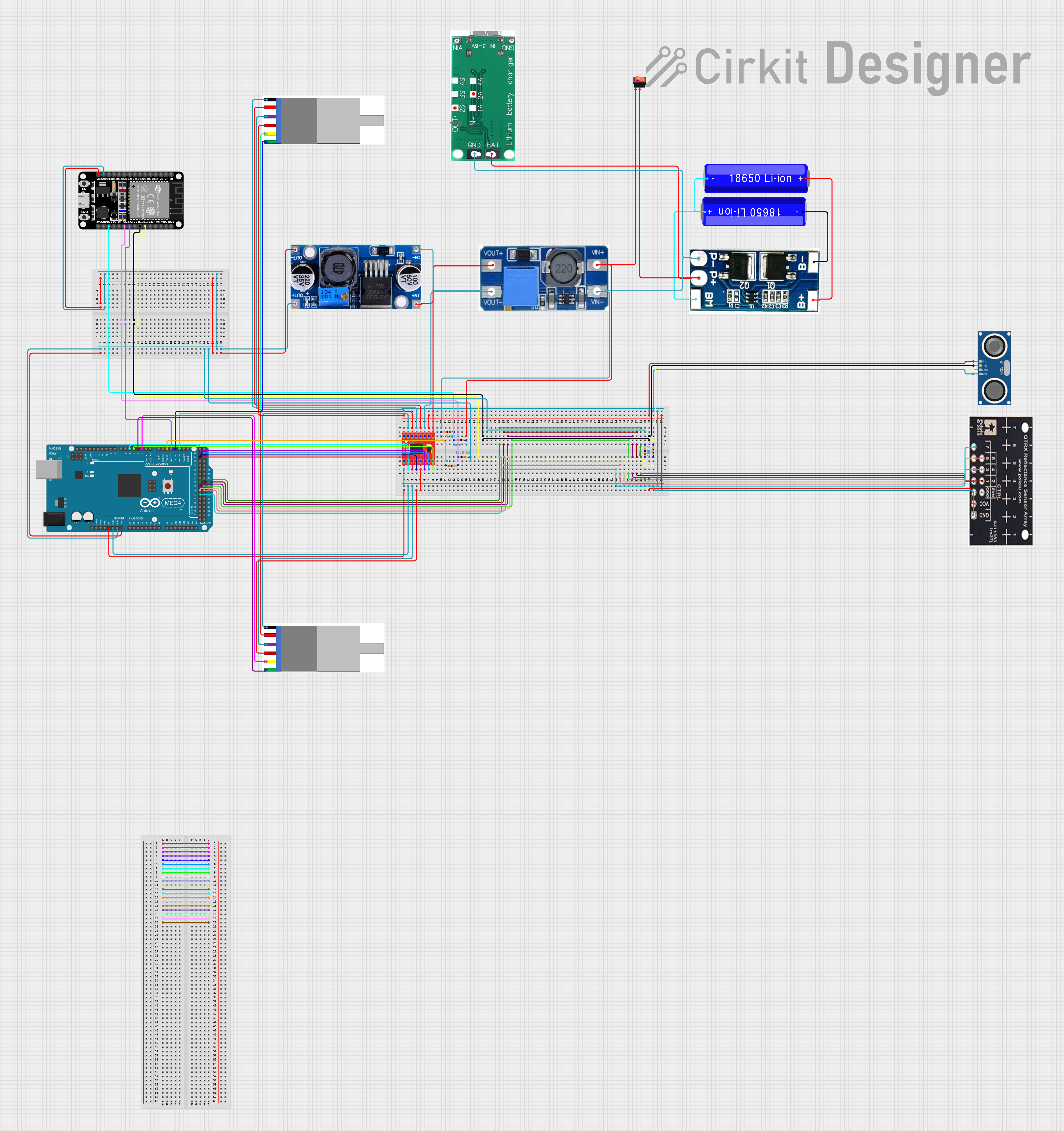
This document provides a detailed overview of a circuit designed to interface various electronic components, including microcontrollers, sensors, motor drivers, and power management modules. The primary controllers in the circuit are an Arduino Mega 2560 and an ESP32 microcontroller, which are responsible for managing inputs and outputs, including driving motors, reading sensor data, and handling power distribution.
Component List
Microcontrollers
- Arduino Mega 2560: A microcontroller board based on the ATmega2560, with numerous digital input/output pins, analog inputs, and a large amount of memory for running complex programs.
- ESP32 (30 pin): A powerful microcontroller with Wi-Fi and Bluetooth capabilities, suitable for IoT projects.
Sensors
- HC-SR04 Ultrasonic Sensor: A sensor that measures distance by emitting ultrasonic waves and measuring the time taken for the echo to return.
- QTRX-HD-07RC Reflectance Sensor Array: A sensor array used for line following or edge detection based on reflectance.
Motors and Encoders
- Gear Motor with integrated Encoder: A motor that provides rotational movement with feedback from an integrated encoder for precise control.
Power Management
- 18650 Li-ion Battery: A rechargeable battery providing a power source for the circuit.
- Lithium Battery Charging Board Type-C: A charging board for lithium batteries with a Type-C input.
- 2S lithium battery protection board module: A protection module for 2S lithium battery configurations, ensuring safe charging and discharging.
- Step Up Boost Power Converter, Adjustable Voltage Regulator: A voltage regulator that steps up the input voltage to a higher, adjustable output voltage.
- Buck Converter, Adjustable Regulator: A voltage regulator that steps down the input voltage to a lower, adjustable output voltage.
Motor Drivers
- Motor Driver 1A Dual TB6612FNG: A dual motor driver capable of driving two motors with up to 1A per channel.
Miscellaneous
- Resistor: A passive component used to limit current or divide voltages in the circuit.
- Rocker Switch: A switch to control the power flow in the circuit.
Wiring Details
Arduino Mega 2560
- VIN: Connected to the VIN of ESP32 and OUT- of Buck Converter.
- GND: Common ground with ESP32, Resistor, and Buck Converter.
- D17 PWM/RX2: Connected to TX2 of ESP32.
- D5 PWM: Connected to PWMB of Motor Driver.
- D25: Connected to BIN2 of Motor Driver.
- D24: Connected to BIN1 of Motor Driver.
- 5V: Connected to STBY of Motor Driver, VCC of QTRX-HD-07RC Reflectance Sensor Array, and VCC of HC-SR04 Ultrasonic Sensor.
- D22: Connected to AIN1 of Motor Driver.
- D23: Connected to AIN2 of Motor Driver.
- D4 PWM: Connected to PWMA of Motor Driver.
- D2 PWM: Connected to Encoder A of Gear Motor with integrated Encoder.
- D3 PWM: Connected to Encoder B of Gear Motor with integrated Encoder.
- D19/RX1: Connected to Encoder A of another Gear Motor with integrated Encoder.
- D18/TX1: Connected to Encoder B of another Gear Motor with integrated Encoder.
- D42, D36, D41, D37, D40, D38, D39: Connected to pins 7, 1, 6, 2, 5, 3, 4 of QTRX-HD-07RC Reflectance Sensor Array respectively.
ESP32 (30 pin)
- Vin: Connected to VIN of Arduino Mega 2560 and OUT- of Buck Converter.
- GND: Common ground with Arduino Mega 2560, Resistor, and Buck Converter.
- D15: Connected to Resistor.
- RX2: Connected to Resistor.
- TX2: Connected to D17 PWM/RX2 of Arduino Mega 2560.
- D18: Connected to TRIG of HC-SR04 Ultrasonic Sensor.
- D19: Connected to Resistor.
Gear Motor with integrated Encoder
- MOTOR -: Connected to B01 of Motor Driver.
- MOTOR+: Connected to B02 of Motor Driver.
- Encoder -: Common ground with Motor Driver, Arduino Mega 2560, QTRX-HD-07RC Reflectance Sensor Array, and HC-SR04 Ultrasonic Sensor.
- Encoder +: Connected to STBY of Motor Driver, VCC of QTRX-HD-07RC Reflectance Sensor Array, and VCC of HC-SR04 Ultrasonic Sensor.
- Encoder A: Connected to D2 PWM of Arduino Mega 2560.
- Encoder B: Connected to D3 PWM of Arduino Mega 2560.
Motor Driver 1A Dual TB6612FNG
- GND: Common ground with Arduino Mega 2560, Gear Motor with integrated Encoder, QTRX-HD-07RC Reflectance Sensor Array, HC-SR04 Ultrasonic Sensor, Step Up Boost Power Converter, and Buck Converter.
- B01: Connected to MOTOR - of Gear Motor with integrated Encoder.
- B02: Connected to MOTOR+ of Gear Motor with integrated Encoder.
- A02: Connected to MOTOR - of another Gear Motor with integrated Encoder.
- A01: Connected to MOTOR+ of another Gear Motor with integrated Encoder.
- VCC: Connected to 5V of Arduino Mega 2560.
- VM: Connected to VOUT+ of Step Up Boost Power Converter and IN+ of Buck Converter.
- PWMA: Connected to D4 PWM of Arduino Mega 2560.
- AIN2: Connected to D23 of Arduino Mega 2560.
- AIN1: Connected to D22 of Arduino Mega 2560.
- STBY: Connected to 5V of Arduino Mega 2560.
- BIN1: Connected to D24 of Arduino Mega 2560.
- BIN2: Connected to D25 of Arduino Mega 2560.
- PWMB: Connected to D5 PWM of Arduino Mega 2560.
Power Management Components
- Step Up Boost Power Converter: VIN- connected to GND of Resistor, GND of Lithium Battery Charging Board, and P- of 2S lithium battery protection board. VIN+ connected to input of Rocker Switch.
- Buck Converter: OUT- connected to VIN of ESP32 and VIN of Arduino Mega 2560. IN- connected to GND of Motor Driver. IN+ connected to VM of Motor Driver.
- Lithium Battery Charging Board Type-C: GND connected to GND of Step Up Boost Power Converter. BAT connected to output of Rocker Switch and P+ of 2S lithium battery protection board.
- 2S lithium battery protection board module: B- connected to - of 18650 Li-ion Battery. P- connected to GND of Step Up Boost Power Converter. BM connected to + of 18650 Li-ion Battery and - of another 18650 Li-ion Battery. B+ connected to + of another 18650 Li-ion Battery.
Sensors
- HC-SR04 Ultrasonic Sensor: TRIG connected to D18 of ESP32. ECHO connected to Resistor. GND and VCC common with other components as described above.
- QTRX-HD-07RC Reflectance Sensor Array: GND and VCC common with other components as described above. Pins 1 to 7 connected to D36, D37, D38, D39, D40, D41, D42 of Arduino Mega 2560 respectively.
Miscellaneous
- Resistor: Various resistors used in the circuit for different purposes, connected to GND, ESP32, and HC-SR04 Ultrasonic Sensor as described above.
- Rocker Switch: Controls the power flow to the Lithium Battery Charging Board and Step Up Boost Power Converter.
Documented Code
Arduino Mega 2560 Code (sketch.ino)
void setup() {
  // put your setup code here, to run once:

}

void loop() {
  // put your main code here, to run repeatedly:

}
Note: The provided code for the Arduino Mega 2560 is a template with empty setup and loop functions. The actual functionality needs to be implemented based on the requirements of the circuit.
ESP32 Code
No code provided for the ESP32 microcontroller.
Note: The ESP32 code needs to be developed and uploaded to the microcontroller to handle tasks such as Wi-Fi/Bluetooth communication, sensor data processing, and motor control.