Arduino UNO Human Detection and Fan Control System with LD2410C Sensor and Relay
Circuit Documentation
Summary
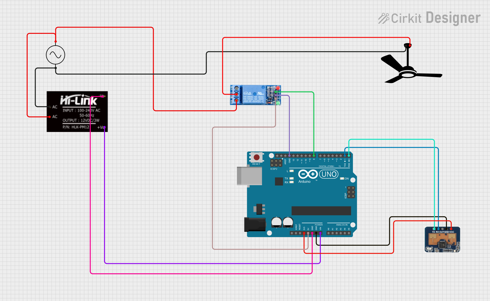
This circuit is designed for human detection and fan control using an Arduino UNO, an LD2410C sensor, a 1 Channel Relay, and a fan. The LD2410C sensor detects human presence and sends a signal to the Arduino UNO, which then activates the relay to turn on the fan. The circuit is powered by an AC supply, which is converted to DC using an HLK-PM12 module.
Component List
Arduino UNO
- Description: A microcontroller board based on the ATmega328P.
- Pins: UNUSED, IOREF, Reset, 3.3V, 5V, GND, Vin, A0, A1, A2, A3, A4, A5, SCL, SDA, AREF, D13, D12, D11, D10, D9, D8, D7, D6, D5, D4, D3, D2, D1, D0
1 Channel Relay 5V
- Description: A relay module that allows control of high voltage devices with a low voltage signal.
- Pins: VCC, GND, IN, NC, COM, NO
HLK-PM12
- Description: A power module that converts AC to DC.
- Pins: +V0, -V0, AC
LD2410C
- Description: A sensor module for human presence detection.
- Pins: RX, OUT, GND, VCC, TX
Fan
- Description: A fan that is controlled by the relay.
- Pins: Neutral, Live
AC Supply
- Description: An AC power supply.
- Pins: +ve, -ve
Wiring Details
Arduino UNO
- 3.3V: Connected to VCC of LD2410C
- 5V: Connected to VCC of 1 Channel Relay 5V
- GND: Connected to GND of LD2410C, GND of 1 Channel Relay 5V, and -V0 of HLK-PM12
- Vin: Connected to +V0 of HLK-PM12
- D8: Connected to IN of 1 Channel Relay 5V
- D1: Connected to RX of LD2410C
- D0: Connected to TX of LD2410C
1 Channel Relay 5V
- VCC: Connected to 5V of Arduino UNO
- GND: Connected to GND of Arduino UNO
- IN: Connected to D8 of Arduino UNO
- COM: Connected to Live of Fan
- NO: Connected to +ve of AC Supply
HLK-PM12
- +V0: Connected to Vin of Arduino UNO
- -V0: Connected to GND of Arduino UNO
- AC: Connected to +ve and -ve of AC Supply
LD2410C
- VCC: Connected to 3.3V of Arduino UNO
- GND: Connected to GND of Arduino UNO
- RX: Connected to D1 of Arduino UNO
- TX: Connected to D0 of Arduino UNO
Fan
- Live: Connected to COM of 1 Channel Relay 5V
- Neutral: Connected to -ve of AC Supply
AC Supply
- +ve: Connected to AC of HLK-PM12 and NO of 1 Channel Relay 5V
- -ve: Connected to AC of HLK-PM12 and Neutral of Fan
Code Documentation
/*
 * Arduino Sketch for Human Detection and Fan Control
 *
 * This code interfaces with an LD2410C sensor to detect human presence. When
 * a human is detected, it activates a relay to turn on a fan. The relay is
 * connected to digital pin 8 of the Arduino UNO, and the LD2410C sensor is
 * connected to the Arduino's 3.3V, GND, RX (D1), and TX (D0) pins.
 */

#define RELAY_PIN 8

void setup() {
  // Initialize serial communication for LD2410C
  Serial.begin(9600);
  // Set relay pin as output
  pinMode(RELAY_PIN, OUTPUT);
  // Ensure the relay is off initially
  digitalWrite(RELAY_PIN, LOW);
}

void loop() {
  // Check if data is available from LD2410C
  if (Serial.available() > 0) {
    // Read the incoming byte
    char incomingByte = Serial.read();
    // Check if the incoming byte indicates human presence
    if (incomingByte == '1') { // Assuming '1' indicates presence
      digitalWrite(RELAY_PIN, HIGH); // Turn on the relay (and the fan)
    } else {
      digitalWrite(RELAY_PIN, LOW); // Turn off the relay (and the fan)
    }
  }
}
This code initializes the serial communication for the LD2410C sensor and sets the relay pin as an output. In the main loop, it checks for incoming data from the sensor. If the data indicates human presence (assumed to be '1'), it turns on the relay, thereby activating the fan. If no presence is detected, it turns off the relay, deactivating the fan.