
LED Indicator System with Power Stabilizer and Measurement Meters
View and Edit Project In Cirkit Designer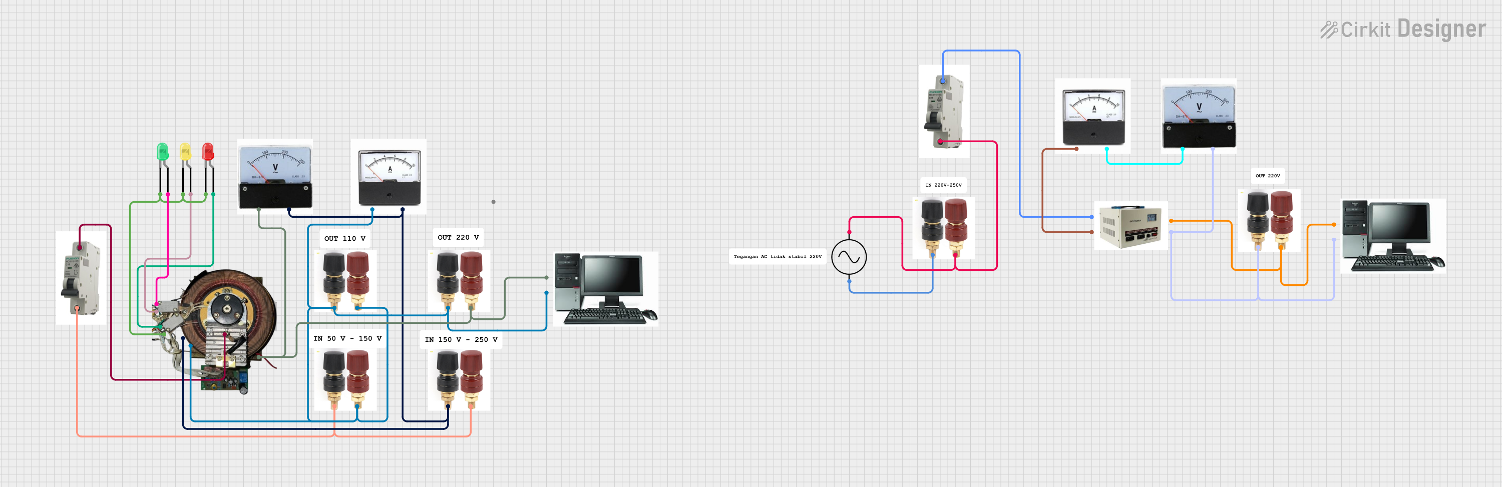
Circuit Documentation
Summary
This document provides a detailed overview of the circuit, including a list of components, wiring details, and any embedded code. The circuit consists of various LEDs, meters, power terminals, a stabilizer module, MCBs, and a computer. The connections between these components are described in detail to ensure proper assembly and functionality.
Component List
LED: Two Pin (green)
- Pins: cathode, anode
LED: Two Pin (red)
- Pins: cathode, anode
LED: Two Pin (yellow)
- Pins: cathode, anode
Terminal Power 555
- Pins: None
Ampere Meter
- Pins: None
Volt Meter
- Pins: None
Modul Stabilizer
- Pins: out +, in pwr, in netral kuning, in netral hijau
MCB
- Pins: IN, OUT
Ac Supply
- Pins: +ve, -ve
Stabilizer
- Pins: servo
Komputer
- Pins: fasa, netral
Wiring Details
LED: Two Pin (green)
Cathode is connected to:
- Cathode of LED: Two Pin (yellow)
- Cathode of LED: Two Pin (red)
- Modul Stabilizer
Anode is connected to:
- Modul Stabilizer
LED: Two Pin (red)
Cathode is connected to:
- Cathode of LED: Two Pin (yellow)
- Cathode of LED: Two Pin (green)
- Modul Stabilizer
Anode is connected to:
- Modul Stabilizer
LED: Two Pin (yellow)
Cathode is connected to:
- Cathode of LED: Two Pin (green)
- Cathode of LED: Two Pin (red)
- Modul Stabilizer
Anode is connected to:
- Modul Stabilizer
Terminal Power 555
Instance 1 is connected to:
- Terminal Power 555 (Instance 2)
- MCB (IN)
- Modul Stabilizer (in netral hijau)
- Terminal Power 555 (Instance 3)
- Ampere Meter
- Terminal Power 555 (Instance 4)
- Komputer (netral)
Instance 2 is connected to:
- Terminal Power 555 (Instance 1)
- Volt Meter
- Modul Stabilizer (in netral kuning)
- Ampere Meter
Instance 3 is connected to:
- Terminal Power 555 (Instance 1)
- Modul Stabilizer (in netral hijau)
- Terminal Power 555 (Instance 4)
- Komputer (netral)
Instance 4 is connected to:
- Terminal Power 555 (Instance 1)
- Modul Stabilizer (in netral hijau)
- Terminal Power 555 (Instance 3)
- Komputer (netral)
Ampere Meter
Instance 1 is connected to:
- Terminal Power 555 (Instance 1)
- Terminal Power 555 (Instance 2)
- Volt Meter
Instance 2 is connected to:
- Stabilizer
- Volt Meter
Volt Meter
Instance 1 is connected to:
- Modul Stabilizer (in netral kuning)
- Terminal Power 555 (Instance 2)
- Ampere Meter
Instance 2 is connected to:
- Modul Stabilizer (out +)
- Terminal Power 555 (Instance 4)
- Komputer (fasa)
Modul Stabilizer
in pwr is connected to:
- MCB (OUT)
in netral hijau is connected to:
- Terminal Power 555 (Instance 1)
- Terminal Power 555 (Instance 3)
- Terminal Power 555 (Instance 4)
- Komputer (netral)
in netral kuning is connected to:
- Volt Meter
- Terminal Power 555 (Instance 2)
- Ampere Meter
out + is connected to:
- Volt Meter
- Terminal Power 555 (Instance 4)
- Komputer (fasa)
MCB
IN is connected to:
- Terminal Power 555 (Instance 1)
- Ac Supply (+ve)
OUT is connected to:
- Modul Stabilizer (in pwr)
- Stabilizer
Ac Supply
+ve is connected to:
- MCB (IN)
-ve is connected to:
- Terminal Power 555 (Instance 4)
Stabilizer
- Servo is connected to:
- MCB (OUT)
- Ampere Meter
Documented Code
There is no embedded code provided for this circuit.
This documentation provides a comprehensive overview of the circuit, including the components used and their interconnections. This should serve as a guide for assembling and understanding the circuit.