
ESP8266-Based Woman Safety Device with OLED Display and GSM Alert
View and Edit Project In Cirkit Designer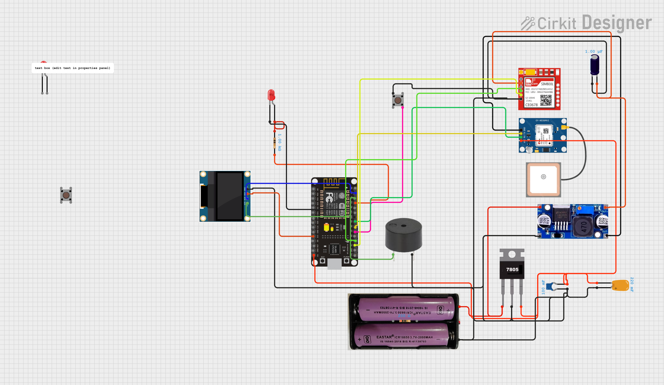
Circuit Documentation
Summary
This document provides a detailed overview of a Woman Safety Device circuit. The circuit includes various components such as a NodeMCU ESP8266, OLED Display, SIM800L GSM Module, Neo6MV2 GPS Module, Buzzer, LEDs, and other supporting components. The device is designed to send an emergency alert when a button is pressed.
Component List
NodeMCU ESP8266
- Description: A microcontroller with built-in Wi-Fi capabilities.
- Pins: D0, D1, D2, D3, D4, 3V3, GND, D5, D6, D7, D8, RX, TX, A0, RSV, SD3, SD2, SD1, CMD, SD0, CLK, EN, RST, VIN
7.4V Battery
- Description: Power source for the circuit.
- Pins: +, -
7805 Voltage Regulator
- Description: Regulates the voltage to 5V.
- Pins: Vin, Gnd, Vout
Ceramic Capacitor
- Description: Provides noise filtering and stability.
- Pins: pin0, pin1
- Properties: Capacitance: 0.1 Farads
Tantalum Capacitor
- Description: Provides noise filtering and stability.
- Pins: -, +
- Properties: Capacitance: 0.22 Farads
0.96" OLED Display
- Description: Displays information.
- Pins: GND, VDD, SCK, SDA
SIM800L GSM Module
- Description: Sends SMS alerts.
- Pins: NET, RST, VCC, RXD, TXD, GND
GPS NEO 6M
- Description: Provides GPS location data.
- Pins: VCC, RX, TX, GND
LM2596 Voltage Regulator
- Description: Regulates the voltage.
- Pins: IN, OUT
Buzzer
- Description: Provides audible alerts.
- Pins: PIN, GND
Resistor (200 Ohms)
- Description: Limits current.
- Pins: pin1, pin2
- Properties: Resistance: 200 Ohms
Resistor (1000 Ohms)
- Description: Limits current.
- Pins: pin1, pin2
- Properties: Resistance: 1000 Ohms
Electrolytic Capacitor
- Description: Provides noise filtering and stability.
- Pins: -, +
- Properties: Capacitance: 0.000001 Farads
Pushbutton
- Description: User input for triggering alerts.
- Pins: Pin 3 (out), Pin 4 (out), Pin 1 (in), Pin 2 (in)
LED: Two Pin (red)
- Description: Visual indicator.
- Pins: cathode, anode
Wiring Details
NodeMCU ESP8266
- D1: Connected to SCK of OLED Display
- D2: Connected to SDA of OLED Display and PIN of Buzzer
- D3: Connected to pin2 of 1000 Ohms Resistor
- D5: Connected to RX of GPS NEO 6M
- D6: Connected to TX of GPS NEO 6M
- D7: Connected to Pin 4 (out) of Pushbutton
- RX: Connected to RXD of SIM800L
- TX: Connected to TXD of SIM800L
- 3V3: Connected to VDD of OLED Display
- GND: Connected to cathode of LED (red)
- VIN: Connected to pin1 of Ceramic Capacitor, VCC of GPS NEO 6M, and Vout of 7805 Voltage Regulator
7.4V Battery
- +: Connected to Vin of 7805 Voltage Regulator and IN of LM2596
- -: Connected to GND of various components
7805 Voltage Regulator
- Vin: Connected to + of 7.4V Battery
- Gnd: Connected to GND of various components
- Vout: Connected to - of Tantalum Capacitor, VCC of GPS NEO 6M, and VIN of NodeMCU ESP8266
Ceramic Capacitor
- pin0: Connected to GND
- pin1: Connected to VIN of NodeMCU ESP8266
Tantalum Capacitor
- -: Connected to Vout of 7805 Voltage Regulator
- +: Connected to GND
0.96" OLED Display
- GND: Connected to GND
- VDD: Connected to 3V3 of NodeMCU ESP8266
- SCK: Connected to D1 of NodeMCU ESP8266
- SDA: Connected to D2 of NodeMCU ESP8266
SIM800L GSM Module
- RXD: Connected to RX of NodeMCU ESP8266
- TXD: Connected to TX of NodeMCU ESP8266
- VCC: Connected to + of Electrolytic Capacitor and OUT of LM2596
- GND: Connected to GND
GPS NEO 6M
- RX: Connected to D5 of NodeMCU ESP8266
- TX: Connected to D6 of NodeMCU ESP8266
- VCC: Connected to Vout of 7805 Voltage Regulator
- GND: Connected to GND
LM2596 Voltage Regulator
- IN: Connected to + of 7.4V Battery
- OUT: Connected to + of Electrolytic Capacitor and VCC of SIM800L
Buzzer
- PIN: Connected to D2 of NodeMCU ESP8266
- GND: Connected to GND
Resistor (200 Ohms)
- pin1: Connected to anode of LED (red)
- pin2: Connected to D3 of NodeMCU ESP8266
Resistor (1000 Ohms)
- pin1: Connected to anode of LED (red)
- pin2: Connected to D3 of NodeMCU ESP8266
Electrolytic Capacitor
- -: Connected to GND
- +: Connected to OUT of LM2596
Pushbutton
- Pin 3 (out): Not connected
- Pin 4 (out): Connected to D7 of NodeMCU ESP8266
- Pin 1 (in): Connected to GND
- Pin 2 (in): Not connected
LED: Two Pin (red)
- cathode: Connected to GND
- anode: Connected to pin1 of 1000 Ohms Resistor
Documented Code
NodeMCU ESP8266 Code
/*
 * Woman Safety Device
 * Components: NodeMCU ESP8266, OLED Display, SIM800L GSM Module,
 * Neo6MV2 GPS Module, Buzzer, LEDs (Red, Red, Blue)
 * Functionality: This code initializes the components and provides
 * basic functionality for the safety device.
 */

#include <Wire.h>
#include <Adafruit_GFX.h>
#include <Adafruit_SSD1306.h>
#include <SoftwareSerial.h>

#define SCREEN_WIDTH 128
#define SCREEN_HEIGHT 64
#define OLED_RESET -1
Adafruit_SSD1306 display(SCREEN_WIDTH, SCREEN_HEIGHT, &Wire, OLED_RESET);

SoftwareSerial sim800l(D1, D2); // RX, TX

#define BUZZER_PIN D7
#define SWITCH_PIN D2

void setup() {
  pinMode(BUZZER_PIN, OUTPUT);
  pinMode(SWITCH_PIN, INPUT);
  digitalWrite(BUZZER_PIN, LOW);

  Serial.begin(115200);
  sim800l.begin(9600);

  if(!display.begin(SSD1306_I2C_ADDRESS, OLED_RESET)) {
    Serial.println(F("SSD1306 allocation failed"));
    for(;;);
  }
  display.display();
  delay(2000);
  display.clearDisplay();
  display.setTextSize(1);
  display.setTextColor(SSD1306_WHITE);
  display.setCursor(0, 0);
  display.println(F("Woman Safety Device"));
  display.display();
}

void loop() {
  if(digitalRead(SWITCH_PIN) == HIGH) {
    digitalWrite(BUZZER_PIN, HIGH);
    sendAlert();
  } else {
    digitalWrite(BUZZER_PIN, LOW);
  }
}

void sendAlert() {
  sim800l.println("AT+CMGF=1");
  delay(1000);
  sim800l.println("AT+CMGS=\"+1234567890\"");
  delay(1000);
  sim800l.print("