
Wi-Fi Controlled Smart Home Automation System with ESP8266, Sensors, and Actuators
View and Edit Project In Cirkit Designer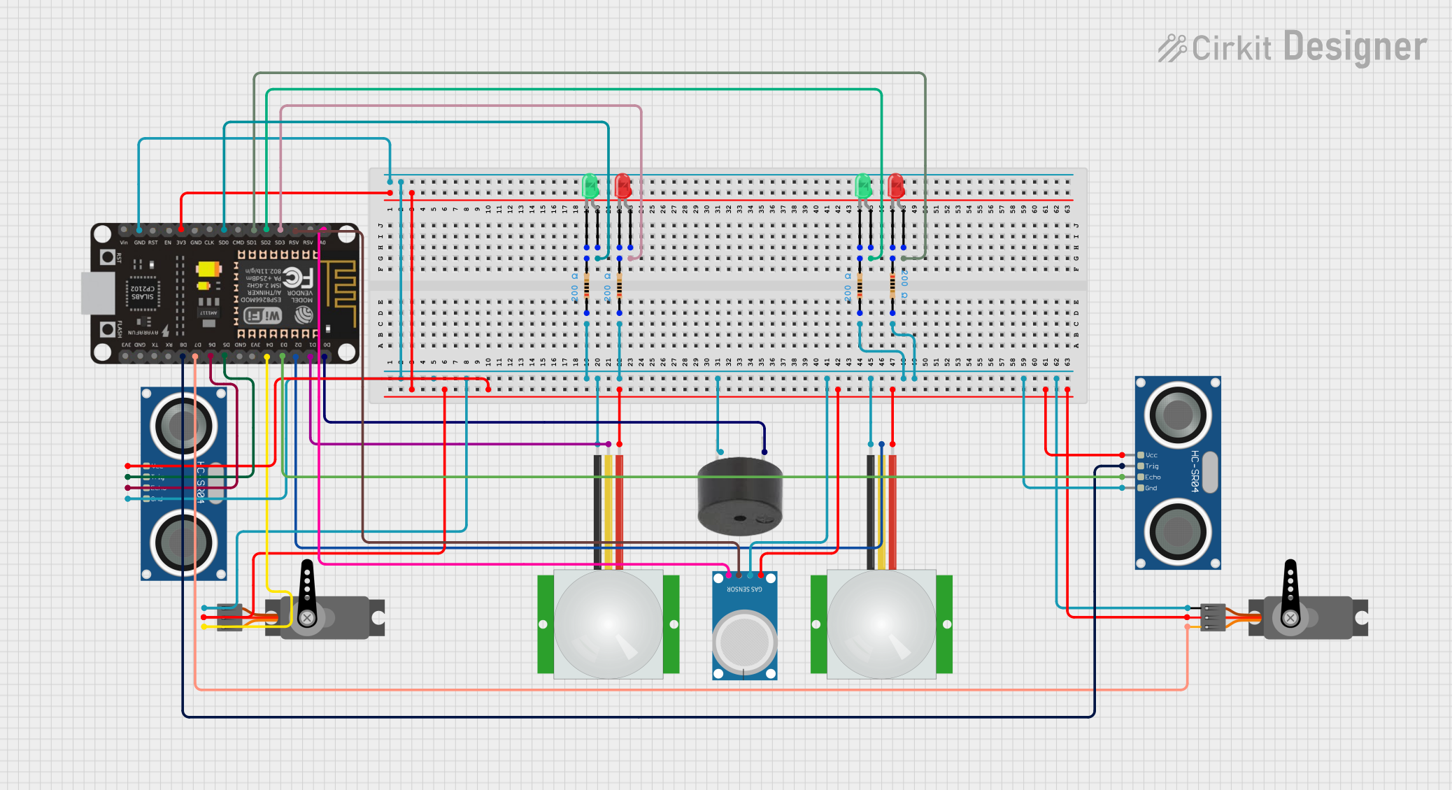
Circuit Documentation
Summary
This circuit involves multiple sensors, actuators, and an ESP8266 NodeMCU microcontroller. The components include servos, PIR sensors, ultrasonic sensors, LEDs, resistors, a buzzer, and an MQ-4 gas sensor. The ESP8266 NodeMCU serves as the central controller, interfacing with all other components to perform various tasks such as motion detection, distance measurement, and gas detection.
Component List
Servo
- Pins: GND, VCC, PWM
- Description: A servo motor used for precise control of angular position.
PIR Sensor
- Pins: VDD, SIG, GND
- Description: A passive infrared sensor used for motion detection.
HC-SR04 Ultrasonic Sensor
- Pins: VCC, TRIG, ECHO, GND
- Description: An ultrasonic sensor used for distance measurement.
Buzzer
- Pins: PIN, GND
- Description: An audio signaling device.
ESP8266 NodeMCU
- Pins: D0, D1, D2, D3, D4, 3V3, GND, D5, D6, D7, D8, RX, TX, A0, RSV, SD3, SD2, SD1, CMD, SD0, CLK, EN, RST, VIN
- Description: A microcontroller with built-in Wi-Fi capabilities.
LED: Two Pin (Red)
- Pins: Cathode, Anode
- Description: A red LED for visual indication.
LED: Two Pin (Green)
- Pins: Cathode, Anode
- Description: A green LED for visual indication.
Resistor
- Pins: Pin1, Pin2
- Description: A resistor with a resistance of 200 Ohms.
MQ-4 Gas Sensor
- Pins: A0, D0, GND, VCC
- Description: A gas sensor used for methane detection.
Wiring Details
Servo
- GND: Connected to the common ground.
- VCC: Connected to the 3.3V power supply.
- PWM:
- One servo's PWM pin is connected to D7 of the ESP8266 NodeMCU.
- Another servo's PWM pin is connected to D4 of the ESP8266 NodeMCU.
PIR Sensor
- VDD: Connected to the 3.3V power supply.
- SIG:
- One PIR sensor's SIG pin is connected to D1 of the ESP8266 NodeMCU.
- Another PIR sensor's SIG pin is connected to D2 of the ESP8266 NodeMCU.
- GND: Connected to the common ground.
HC-SR04 Ultrasonic Sensor
- VCC: Connected to the 3.3V power supply.
- TRIG:
- One ultrasonic sensor's TRIG pin is connected to D5 of the ESP8266 NodeMCU.
- Another ultrasonic sensor's TRIG pin is connected to D8 of the ESP8266 NodeMCU.
- ECHO:
- One ultrasonic sensor's ECHO pin is connected to D6 of the ESP8266 NodeMCU.
- Another ultrasonic sensor's ECHO pin is connected to D3 of the ESP8266 NodeMCU.
- GND: Connected to the common ground.
Buzzer
- PIN: Connected to D0 of the ESP8266 NodeMCU.
- GND: Connected to the common ground.
ESP8266 NodeMCU
- 3V3: Connected to the VCC pins of the servos, PIR sensors, ultrasonic sensors, and MQ-4 gas sensor.
- GND: Connected to the common ground.
- D0: Connected to the PIN of the buzzer.
- D1: Connected to the SIG of one PIR sensor.
- D2: Connected to the SIG of another PIR sensor.
- D3: Connected to the ECHO of one ultrasonic sensor.
- D4: Connected to the PWM of one servo.
- D5: Connected to the TRIG of one ultrasonic sensor.
- D6: Connected to the ECHO of another ultrasonic sensor.
- D7: Connected to the PWM of another servo.
- D8: Connected to the TRIG of another ultrasonic sensor.
- A0: Connected to the A0 of the MQ-4 gas sensor.
- RSV: Connected to the D0 of the MQ-4 gas sensor.
- SD0: Connected to the anode of a green LED.
- SD1: Connected to the anode of a red LED.
- SD2: Connected to the anode of another green LED.
- SD3: Connected to the anode of another red LED.
LED: Two Pin (Red)
- Anode:
- One red LED's anode is connected to SD3 of the ESP8266 NodeMCU.
- Another red LED's anode is connected to SD1 of the ESP8266 NodeMCU.
- Cathode:
- One red LED's cathode is connected to pin1 of a resistor.
- Another red LED's cathode is connected to pin1 of another resistor.
LED: Two Pin (Green)
- Anode:
- One green LED's anode is connected to SD2 of the ESP8266 NodeMCU.
- Another green LED's anode is connected to SD0 of the ESP8266 NodeMCU.
- Cathode:
- One green LED's cathode is connected to pin2 of a resistor.
- Another green LED's cathode is connected to pin2 of another resistor.
Resistor
- Pin1:
- One resistor's pin1 is connected to the cathode of a red LED.
- Another resistor's pin1 is connected to the cathode of another red LED.
- Pin2:
- One resistor's pin2 is connected to the common ground.
- Another resistor's pin2 is connected to the common ground.
MQ-4 Gas Sensor
- A0: Connected to A0 of the ESP8266 NodeMCU.
- D0: Connected to RSV of the ESP8266 NodeMCU.
- GND: Connected to the common ground.
- VCC: Connected to the 3.3V power supply.
Code
No code provided for this circuit.
This documentation provides a comprehensive overview of the circuit, including a summary, component list, wiring details, and code section. Each component is described, and its connections are detailed to ensure clarity and ease of understanding.