
Circuit Documentation
Summary of the Circuit
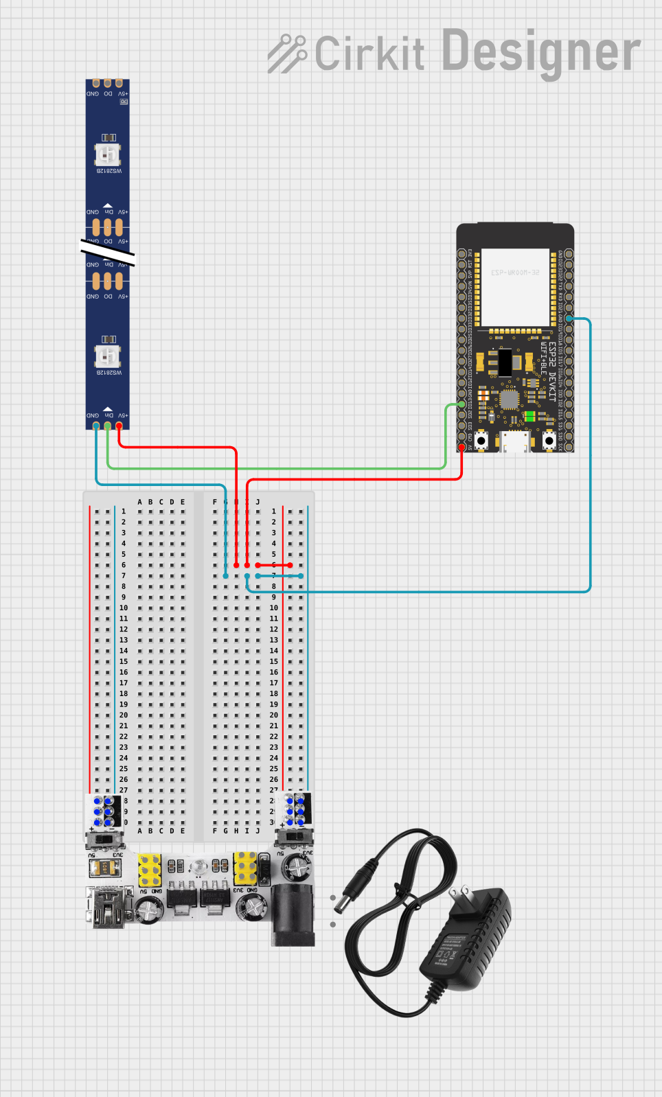
This circuit is designed to control a WS2812 RGB LED strip using an ESP32 Wroom microcontroller. The ESP32 is powered by a 5V supply from a breadboard power module, which also provides the necessary 5V to the LED strip. The ground connections are unified across all components to complete the circuit. The ESP32's GPIO13 is used to send data signals to the LED strip's data input pin.
Component List
ESP32 Wroom
- Description: A powerful microcontroller with Wi-Fi and Bluetooth capabilities, suitable for a wide range of IoT applications.
- Pins: 3V3, Reset, GPIOs, GND, 5V, TXD0, RXD0, SCL, SDA, and others.
12v Power Supply
- Description: Provides a stable 12V power source for circuits that require higher voltage levels.
- Pins: + (positive), - (negative).
WS2812 RGB LED Strip
- Description: An addressable LED strip that allows for individual control of each RGB LED, enabling a wide spectrum of colors and effects.
- Pins: DIN (Data Input), 5V, GND, DO (Data Output).
Breadboard Power Module (3.3/5V)
- Description: A module that supplies either 3.3V or 5V to power a breadboard or other components in a circuit.
- Pins: + (positive), - (negative), VCC (5V), GND, VCC (3.3V).
Wiring Details
ESP32 Wroom
- 5V: Connected to the 5V output from the breadboard power module.
- GND: Connected to the ground rail of the breadboard power module.
- GPIO13: Connected to the DIN pin of the WS2812 RGB LED strip.
12v Power Supply
- + (positive): Not connected in this circuit.
- - (negative): Not connected in this circuit.
WS2812 RGB LED Strip
- DIN (Data Input): Connected to GPIO13 of the ESP32 Wroom.
- 5V: Connected to the 5V output from the breadboard power module.
- GND: Connected to the ground rail of the breadboard power module.
- DO (Data Output): Not connected in this circuit.
Breadboard Power Module (3.3/5V)
- + (positive): Connected to the 5V pin of the ESP32 Wroom and the 5V pin of the WS2812 RGB LED strip.
- - (negative): Connected to the GND pin of the ESP32 Wroom and the GND pin of the WS2812 RGB LED strip.
- VCC (5V): Not used in this circuit.
- GND: Not used in this circuit.
- VCC (3.3V): Not used in this circuit.
Documented Code
There is no code provided for the microcontroller in this circuit. To control the WS2812 RGB LED strip, code would typically be written to initialize the microcontroller's GPIO pin for digital output and to send data signals that conform to the timing requirements of the WS2812 protocol. This would involve setting up a timer or using a dedicated library that handles the timing and data formatting for driving the LED strip.