
Arduino UNO Controlled Solenoid Valve with RGB LED and Spectral Sensor
View and Edit Project In Cirkit Designer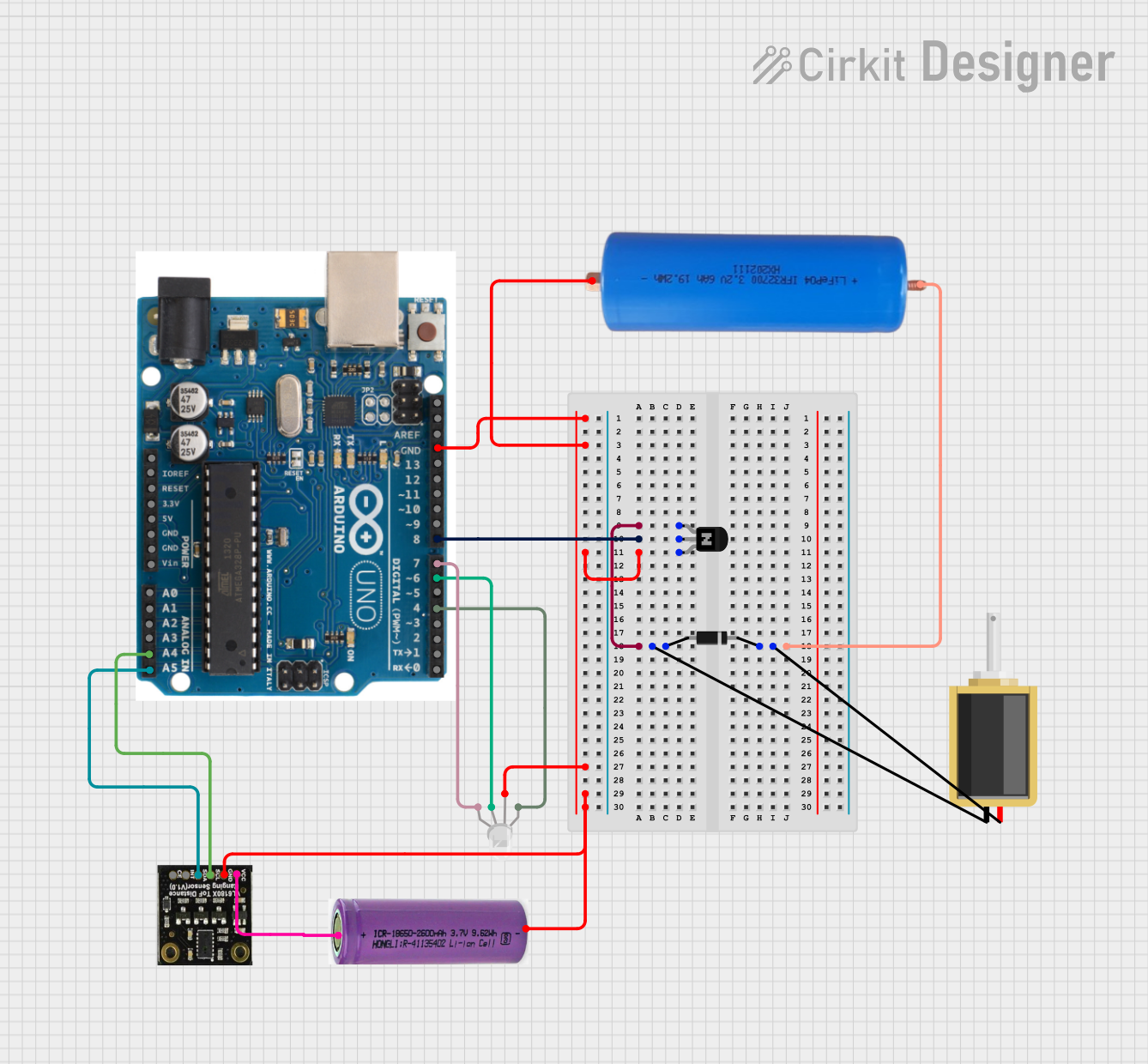
Circuit Documentation
Summary
This circuit involves an Arduino UNO microcontroller controlling an RGB LED, a solenoid, and an NPN transistor. The circuit also includes a diode, a LifePo4 battery, a 3.3V battery, and a SEN0427 sensor. The Arduino UNO is programmed to control the solenoid valve based on timing and user input, and to measure and log spectral data using the SEN0427 sensor.
Component List
NPN Transistor (EBC)
- Description: A standard NPN transistor with emitter, base, and collector pins.
- Pins: emitter, base, collector
Diode
- Description: A standard diode with cathode and anode pins.
- Pins: cathode, anode
LifePo4 3.2V 6Ah
- Description: A 3.2V 6Ah LifePo4 battery.
- Pins: Pin (+), Pin (-)
Solenoid
- Description: A solenoid with two pins.
- Pins: pin1, pin2
Arduino UNO
- Description: A microcontroller board based on the ATmega328P.
- Pins: SDA, AREF, GND, 13, 12, 11, 10, 9, 8, 7, 6, 5, 4, 3, 2, 1, 0, A5, A4, A3, A2, A1, A0, Vin, 5V, 3.3V, RESET, IOREF, SCL
RGB LED (Wokwi compatible)
- Description: An RGB LED with four pins: Red, Common, Green, and Blue.
- Pins: R, COM, G, B
SEN0427
- Description: A sensor module with VCC, GND, SCL, SDA, INT, and CE pins.
- Pins: VCC, GND, SCL, SDA, INT, CE
3.3V Battery
- Description: A 3.3V battery.
- Pins: +, -
Wiring Details
NPN Transistor (EBC)
Emitter is connected to:
- Anode of the Diode
- Pin1 of the Solenoid
Base is connected to:
- Pin 8 of the Arduino UNO
Collector is connected to:
- GND of the Arduino UNO
- Pin (-) of the LifePo4 3.2V 6Ah
- COM of the RGB LED
- GND of the SEN0427
-
- of the 3.3V Battery
Diode
Anode is connected to:
- Emitter of the NPN Transistor
- Pin1 of the Solenoid
Cathode is connected to:
- Pin2 of the Solenoid
- Pin (+) of the LifePo4 3.2V 6Ah
LifePo4 3.2V 6Ah
Pin (+) is connected to:
- Cathode of the Diode
- Pin2 of the Solenoid
Pin (-) is connected to:
- Collector of the NPN Transistor
- GND of the Arduino UNO
- COM of the RGB LED
- GND of the SEN0427
-
- of the 3.3V Battery
Solenoid
Pin1 is connected to:
- Anode of the Diode
- Emitter of the NPN Transistor
Pin2 is connected to:
- Cathode of the Diode
- Pin (+) of the LifePo4 3.2V 6Ah
Arduino UNO
Pin 8 is connected to:
- Base of the NPN Transistor
GND is connected to:
- Collector of the NPN Transistor
- Pin (-) of the LifePo4 3.2V 6Ah
- COM of the RGB LED
- GND of the SEN0427
-
- of the 3.3V Battery
Pin 7 is connected to:
- B of the RGB LED
Pin 6 is connected to:
- G of the RGB LED
Pin 4 is connected to:
- R of the RGB LED
Pin A5 is connected to:
- SDA of the SEN0427
Pin A4 is connected to:
- SCL of the SEN0427
RGB LED (Wokwi compatible)
R is connected to:
- Pin 4 of the Arduino UNO
COM is connected to:
- Collector of the NPN Transistor
- GND of the Arduino UNO
- Pin (-) of the LifePo4 3.2V 6Ah
- GND of the SEN0427
-
- of the 3.3V Battery
G is connected to:
- Pin 6 of the Arduino UNO
B is connected to:
- Pin 7 of the Arduino UNO
SEN0427
VCC is connected to:
-
- of the 3.3V Battery
-
GND is connected to:
- Collector of the NPN Transistor
- GND of the Arduino UNO
- Pin (-) of the LifePo4 3.2V 6Ah
- COM of the RGB LED
-
- of the 3.3V Battery
SCL is connected to:
- Pin A4 of the Arduino UNO
SDA is connected to:
- Pin A5 of the Arduino UNO
3.3V Battery
+ is connected to:
- VCC of the SEN0427
- is connected to:
- Collector of the NPN Transistor
- GND of the Arduino UNO
- Pin (-) of the LifePo4 3.2V 6Ah
- COM of the RGB LED
- GND of the SEN0427
Code Documentation
#include "DFRobot_AS7341.h"
#include <math.h>  // For log10()

DFRobot_AS7341 as7341;
int redPin = 4;
int greenPin = 6;
int bluePin = 7;
int valvePin = 8;  // Pin controlling the valve

// Declare the variables here
DFRobot_AS7341::sModeOneData_t data1;
DFRobot_AS7341::sModeTwoData_t data2;
float absorbance;
float transmittance;

// Timing variables for valve control
unsigned long previousMillis = 0;
const long totalInterval = 45000;  // Total interval of 45 seconds
const long openDuration = 1000;   // Valve open duration of 1 second

// Purge mode variables
bool purgeMode = false;
unsigned long purgeStartTime = 0;
const long purgeDuration = 120000;  // 2 minutes (120,000 milliseconds)

void setup(void) {
  pinMode(redPin, OUTPUT);
  pinMode(greenPin, OUTPUT);
  pinMode(bluePin, OUTPUT);
  pinMode(valvePin, OUTPUT);  // Set the valve pin as an output
  digitalWrite(valvePin, LOW);  // Ensure the valve is initially closed

  Serial.begin(9600);
  // Detect if IIC can communicate properly
  while (as7341.begin() != 0) {
    Serial.println("IIC init failed, please check if the wire connection is correct");
    delay(1000);
  }

  Serial.println("System ready. Type 'purge' to start purging for 2 minutes.");
}

void setColor(int redValue, int greenValue, int blueValue) {
  analogWrite(redPin, redValue);
  analogWrite(greenPin, greenValue);
  analogWrite(bluePin, blueValue);
}

void loop() {
  // Check for serial input
  if (Serial.available() > 0) {
    String command = Serial.readStringUntil('\n');
    command.trim(); // Remove any leading/trailing whitespace

    if (command.equalsIgnoreCase("purge")) {
      purgeMode = true;
      purgeStartTime = millis();
      Serial.println("Purge mode activated. Solenoid will remain open for 2 minutes.");
      digitalWrite(valvePin, HIGH); // Open the solenoid
    }
  }

  // Handle purge mode
  if (purgeMode) {
    if (millis() - purgeStartTime >= purgeDuration) {
      // End purge mode after 2 minutes
      purgeMode = false;
      digitalWrite(valvePin, LOW); // Close the solenoid
      Serial.println("Purge mode complete. Returning to normal operation.");
    } else {
      // Keep the solenoid open during purge mode
      return;
    }
  }

  // Timed valve control logic (normal operation)
  unsigned long currentMillis = millis();
  if (currentMillis - previousMillis >= total