
Arduino Nano Controlled Sound and Light Effects System with NeoPixel LEDs
View and Edit Project In Cirkit Designer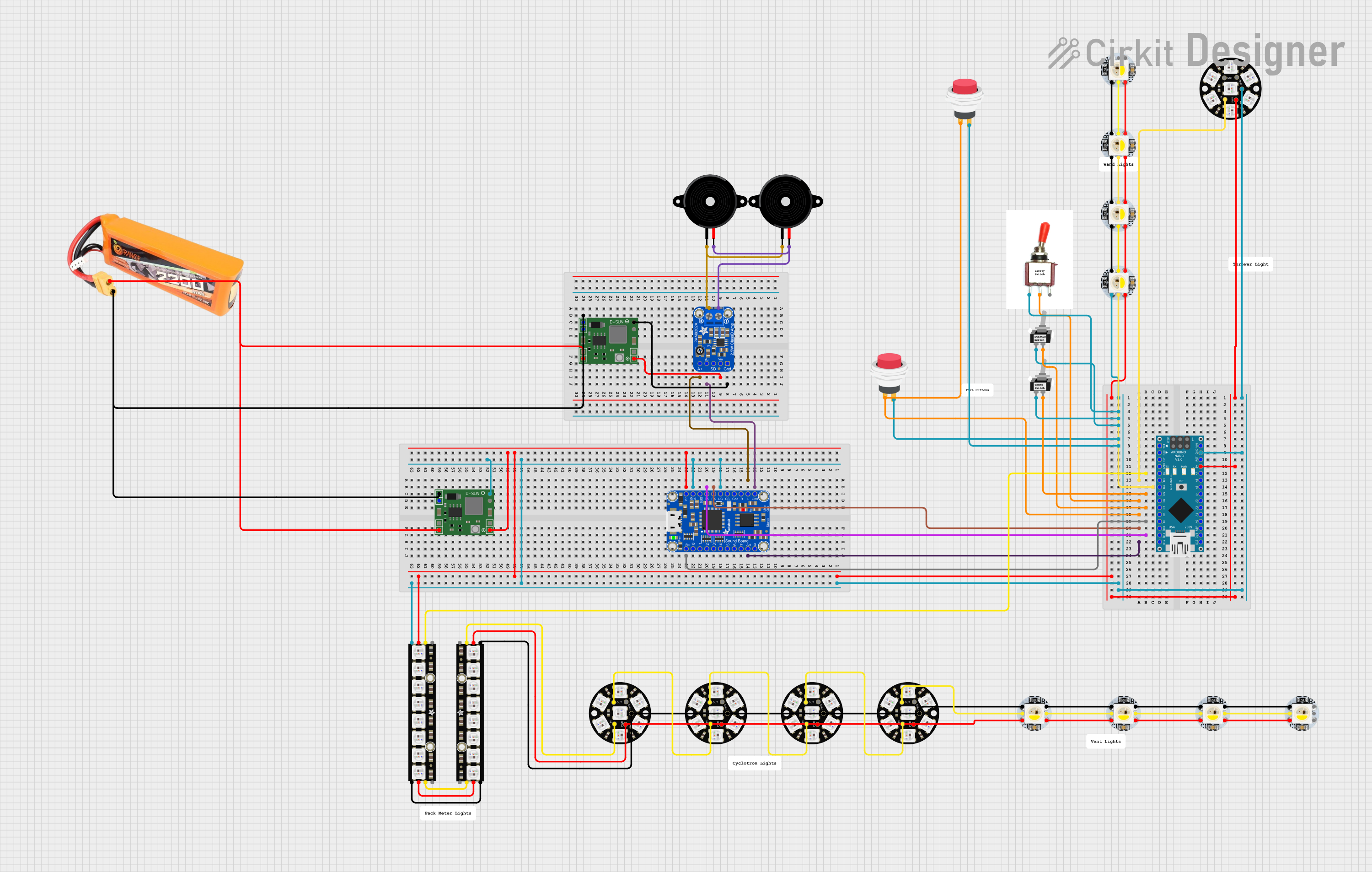
Circuit Documentation
Summary
The circuit in question is designed to control a series of WS2812B White LEDs, Adafruit NeoPixel Jewels, and Adafruit NeoPixel Sticks, all of which are individually addressable RGB LEDs. The circuit is controlled by an Arduino Nano microcontroller, which is responsible for driving the LED animations and interfacing with an Adafruit Audio FX Mini Sound Board for audio playback. The circuit also includes toggle switches and push switches for user interaction, a piezo speaker for audio output, a lipo battery for power supply, and MP1584EN Power Regulator Boards to regulate the power supply to the components. The Arduino Nano runs embedded code to manage the LED animations, sound playback, and user inputs.
Component List
LEDs
- WS2812B White LED: Individually addressable RGB LED with 5V, GND, Data In (DIn), and Data Out (DOut) pins.
- Adafruit NeoPixel Jewel: Compact board with 7 x WS2812 RGB LEDs, with GND, Data In (IN), Data Out (OUT), and Power (VDD) pins.
- Adafruit NeoPixel Stick: A strip of 8 x WS2812 RGB LEDs, with GND, Data Out (DATAOUT), Power (+5V), and Data In (DATAIN) pins.
Controls
- Toggle Switch SPST: Single Pole Single Throw switch with L1 and Common (COM) pins.
- 2Pin Push Switch: A push-button switch with Input (+) and Output (+) pins.
Sound
- Adafruit Audio FX Mini Sound Board: A sound board with multiple GPIO pins, including Reset (RST), Power (VIN), Ground (GND), and audio out pins (L_AC, R_AC).
- Piezo Speaker: A simple speaker with two pins (pin1, pin2) for audio output.
- Adafruit PAM8302: An audio amplifier board with pins for Ground (GND), Power (VCC), Shutdown control (SD), Audio Input (AIN- and AIN+), and Audio Output (VO- and VO+).
Power
- Lipo Battery 2200mAh 30C: A rechargeable battery with VCC and GND pins.
- MP1584EN Power Regulator Board: A power regulator board with Input (- and +) and Output (- and +) pins.
Microcontroller
- Arduino Nano: A small microcontroller board with various digital and analog I/O pins.
Miscellaneous
- Comment: A placeholder for comments or notes within the circuit, not an actual physical component.
Wiring Details
WS2812B White LED
- 5V: Connected to the 5V power supply.
- GND: Connected to the ground.
- DIn: Connected to a digital output pin on the Arduino Nano for data input.
- DOut: Connected to the next LED's DIn or left unconnected if it is the last LED in the chain.
Adafruit NeoPixel Jewel
- GND: Connected to the ground.
- IN: Connected to a digital output pin on the Arduino Nano for data input.
- OUT: Connected to the next LED's IN or left unconnected if it is the last in the chain.
- VDD: Connected to the 5V power supply.
Adafruit NeoPixel Stick
- GND: Connected to the ground.
- DATAOUT: Connected to the next LED's DATAIN or left unconnected if it is the last in the chain.
- +5V: Connected to the 5V power supply.
- DATAIN: Connected to a digital output pin on the Arduino Nano for data input.
Toggle Switch SPST
- L1: Connected to the 5V power supply.
- COM: Connected to a digital input pin on the Arduino Nano.
2Pin Push Switch
- Input +: Connected to a digital input pin on the Arduino Nano.
- Output +: Connected to the 5V power supply.
Adafruit Audio FX Mini Sound Board
- RST: Connected to a digital output pin on the Arduino Nano for reset control.
- VIN: Connected to the 5V power supply.
- GND: Connected to the ground.
- L_AC/R_AC: Connected to the Adafruit PAM8302 audio amplifier's AIN- and AIN+ pins respectively.
Piezo Speaker
- pin1/pin2: Connected to the Adafruit PAM8302 audio amplifier's VO- and VO+ pins respectively.
Adafruit PAM8302
- GND: Connected to the ground.
- VCC: Connected to the 5V power supply.
- SD: Not connected or controlled by a digital output pin on the Arduino Nano for shutdown control.
- AIN-: Connected to the Adafruit Audio FX Mini Sound Board's GND pin.
- AIN+: Connected to the Adafruit Audio FX Mini Sound Board's L_AC pin.
- VO-: Connected to the Piezo Speaker's pin2.
- VO+: Connected to the Piezo Speaker's pin1.
MP1584EN Power Regulator Board
- IN -: Connected to the lipo battery's GND pin.
- IN +: Connected to the lipo battery's VCC pin.
- OUT -: Connected to the ground of the circuit.
- OUT +: Connected to the 5V power supply line of the circuit.
Lipo Battery 2200mAh 30C
- VCC: Connected to the MP1584EN Power Regulator Board's IN + pin.
- GND: Connected to the MP1584EN Power Regulator Board's IN - pin.
Arduino Nano
- Various digital and analog pins connected to the components as per the functionality required by the embedded code.
Documented Code
The embedded code for the Arduino Nano is written in C++ and is designed to control the LEDs and sound board based on the inputs from the switches and buttons. The code includes libraries for managing the Adafruit NeoPixel LEDs (Adafruit_NeoPixel.h) and the Adafruit Sound Board (Adafruit_Soundboard.h). It also uses a custom queue library (QueueArray.h) to manage audio track playback.
The main functionality of the code includes:
- Initializing the NeoPixel LEDs and setting their brightness.
- Reading the state of the switches and buttons to trigger LED animations and sound playback.
- Controlling the Adafruit Sound Board to play, pause, and stop audio tracks.
- Implementing LED animations for different states such as power on, idle, firing, and shutdown.
- Managing audio playback with a queue system to avoid repeating tracks.
The code is structured with setup and loop functions, as well as helper functions for LED control, sound playback, and animations. Comments within the code provide additional details on the functionality of each section.
Note: The actual code is not included in this document but is referenced by file names such as Neutrino_Wand.ino, QueueArray.h, and Adafruit_Soundboard.h. The code should be reviewed in conjunction with this documentation for a complete understanding of the circuit's operation.