
Arduino Pro Mini Based Health Monitoring System with OLED Display and Infrared Temperature Sensor
View and Edit Project In Cirkit Designer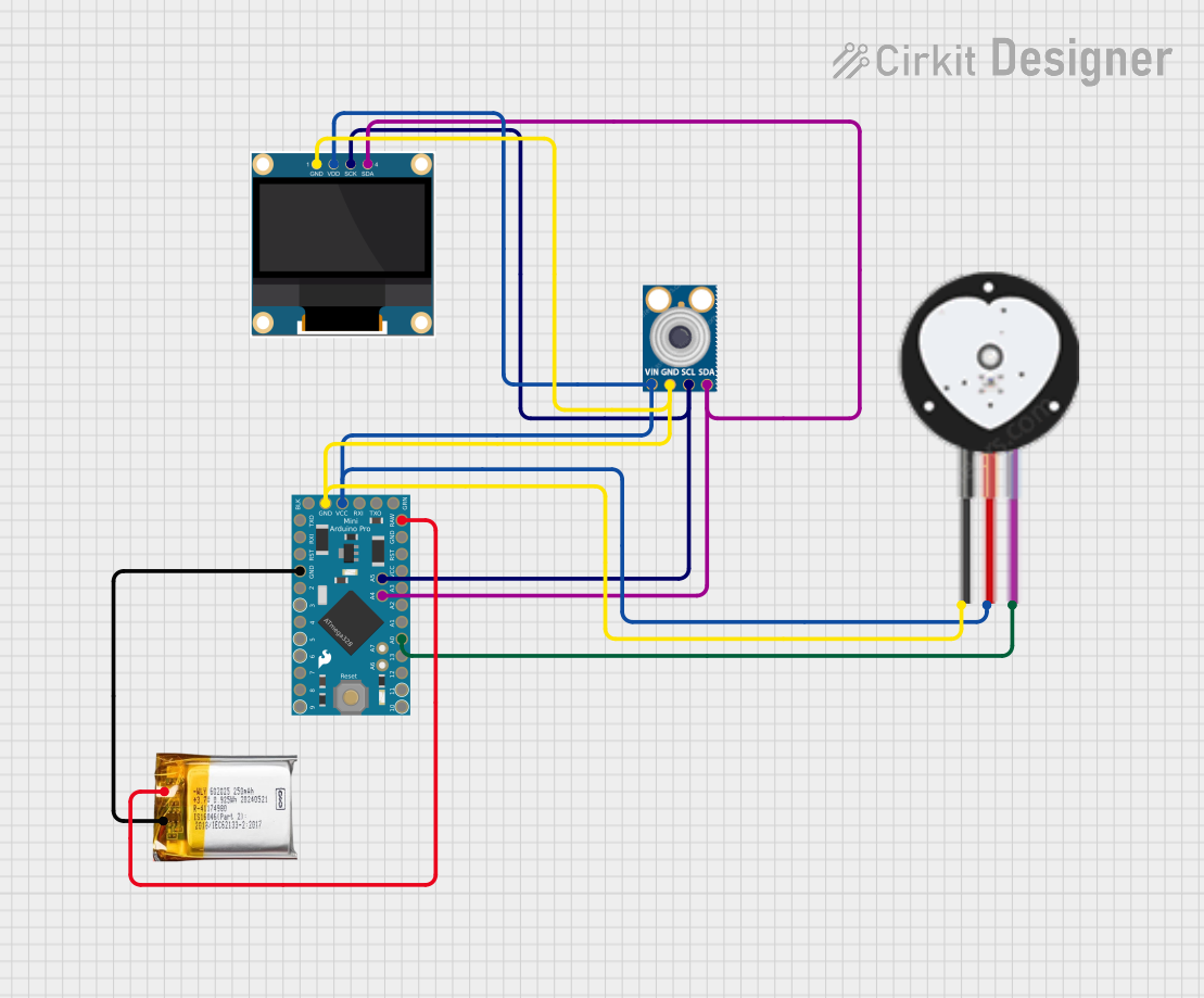
Circuit Documentation
Summary
The circuit in question is designed around an Arduino Pro Mini microcontroller and includes a variety of sensors and a display module. The circuit is powered by a 3.7v LiPo battery and is capable of reading heart pulse signals and temperature data, which can be displayed on a 0.96" OLED screen. The Arduino Pro Mini serves as the central processing unit, interfacing with the Heart Pulse Sensor and mlx90614 temperature sensor via analog and I2C communication, respectively. The OLED display also communicates with the Arduino via I2C. The circuit is designed for low power consumption, suitable for wearable or portable applications.
Component List
Arduino Pro Mini
- Microcontroller board based on the ATmega328
- Operating Voltage: 3.3V or 5V (depending on the model)
- Digital I/O Pins: 14 (of which 6 provide PWM output)
- Analog Input Pins: 8
- Clock Speed: 8 MHz or 16 MHz
0.96" OLED
- Small OLED display for visual output
- Communication: I2C
- Operating Voltage: Typically 3.3V to 5V
Heart Pulse Sensor
- Sensor for detecting heartbeats
- Operating Voltage: Typically 3.3V to 5V
- Output: Analog signal corresponding to heart pulse
mlx90614
- Infrared thermometer for non-contact temperature measurements
- Communication: I2C
- Operating Voltage: Typically 3.3V to 5V
3.7v LiPo Battery
- Rechargeable lithium polymer battery
- Nominal Voltage: 3.7V
- Used as the power source for the circuit
Wiring Details
Arduino Pro Mini
VCCconnected to the VCC of Heart Pulse Sensor, VIN of mlx90614, and VDD of OLEDGNDconnected to the GND of all components and the negative terminal of the LiPo batteryA4 (SDA)connected to SDA of mlx90614 and SDA of OLED for I2C communicationA5 (SCL)connected to SCL of mlx90614 and SCK of OLED for I2C communicationRAWconnected to the positive terminal of the LiPo battery for powerA0connected to the SIGNAL of the Heart Pulse Sensor for reading pulse data
0.96" OLED
GNDconnected to the GND of Arduino Pro MiniVDDconnected to the VCC of Arduino Pro MiniSCKconnected to A5 (SCL) of Arduino Pro MiniSDAconnected to A4 (SDA) of Arduino Pro Mini
Heart Pulse Sensor
GNDconnected to the GND of Arduino Pro MiniVCCconnected to the VCC of Arduino Pro MiniSIGNALconnected to A0 of Arduino Pro Mini
mlx90614
GNDconnected to the GND of Arduino Pro MiniVINconnected to the VCC of Arduino Pro MiniSCLconnected to A5 (SCL) of Arduino Pro MiniSDAconnected to A4 (SDA) of Arduino Pro Mini
3.7v LiPo Battery
GNDconnected to the GND of Arduino Pro Mini+Veconnected to the RAW of Arduino Pro Mini
Documented Code
Arduino Pro Mini (sketch.ino)
void setup() {
  // put your setup code here, to run once:

}

void loop() {
  // put your main code here, to run repeatedly:

}
Additional Notes
- The provided code is a template and does not include specific functionality. It needs to be populated with the initialization and operational code for the sensors and display.
- The
setup()function is used for initializing settings, pin modes, and starting communication protocols. - The
loop()function will contain the main logic for reading sensor data, processing it, and displaying it on the OLED screen. - I2C communication is set up on pins A4 (SDA) and A5 (SCL) for the mlx90614 and OLED display.
- Analog readings from the Heart Pulse Sensor are taken from pin A0.
This documentation provides an overview of the circuit, including the components used, their wiring, and a basic code structure for the Arduino Pro Mini. Further development of the code is required to achieve the desired functionality.