
Arduino Mega 2560-Based Robotic System with Stepper Motors and IR Sensors
View and Edit Project In Cirkit Designer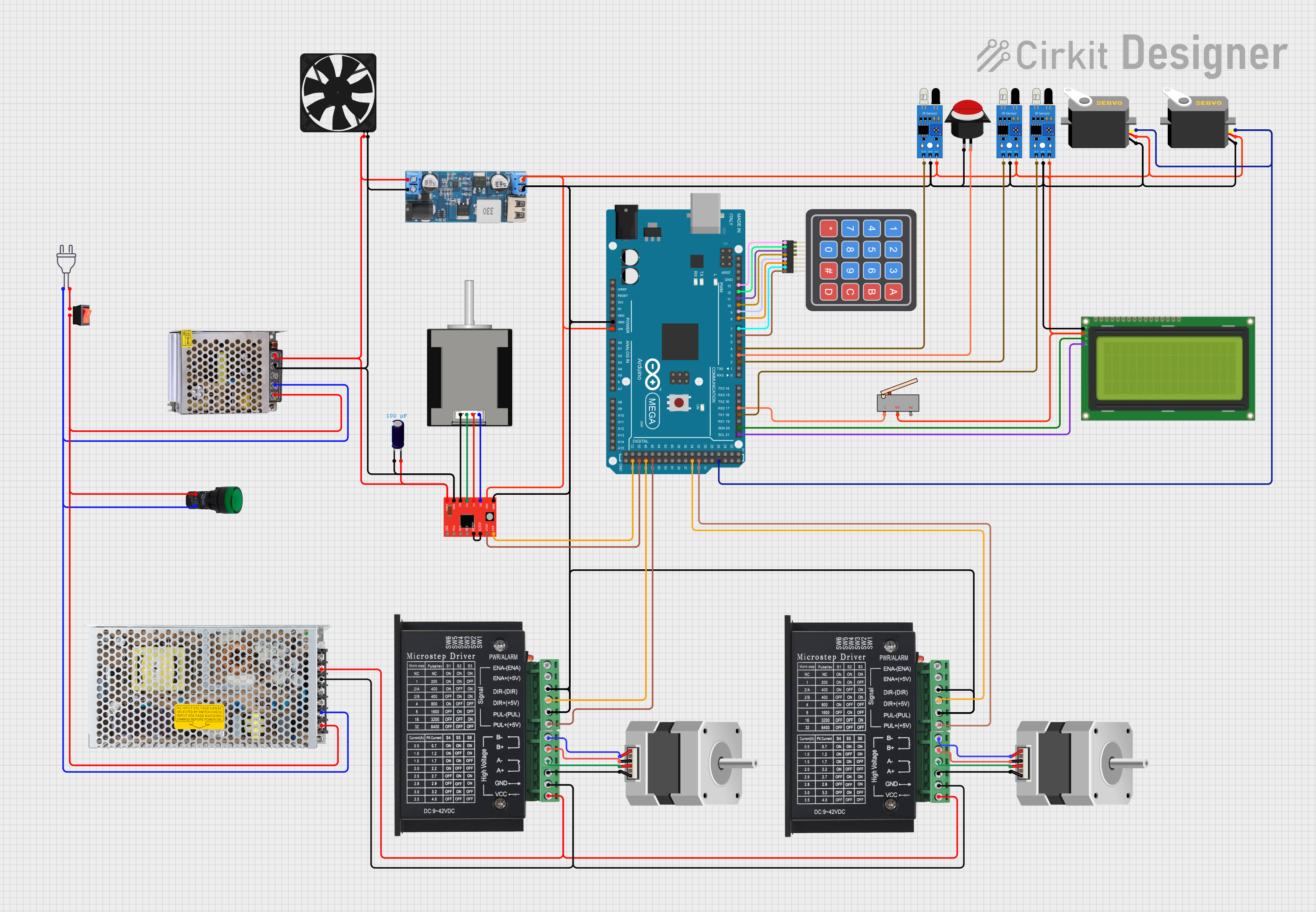
Circuit Documentation
Summary
This document provides a detailed overview of a circuit that includes various components such as sensors, servos, stepper motors, a microcontroller, and other peripherals. The circuit is designed to interface with an Arduino Mega 2560 microcontroller, which controls the various components. The power supply is managed through a 12V to 5V step-down converter, and the circuit includes multiple sensors and actuators for various functionalities.
Component List
12V to 5V Step Down Power Converter
- Description: Converts 12V input to 5V output.
- Pins: VIN 9v-36v, VIN+, VIN-, USB OUTPUT 5V, 5v OUTPUT, GND
Servo
- Description: Standard servo motor.
- Pins: gnd, vcc, pulse
NEMA23
- Description: High-torque stepper motor.
- Pins: D, B, C, A
IR Sensor
- Description: Infrared sensor for object detection.
- Pins: out, gnd, vcc
LCD 20x4 I2C
- Description: 20x4 character LCD with I2C interface.
- Pins: GND, 5v, SCA, SCL
Arduino Mega 2560
- Description: Microcontroller board based on the ATmega2560.
- Pins: IOREF, RESET, 3V3, 5V, GND, VIN, A0-A15, D0-D53, AREF, SDA, SCL
Fan_Fyp
- Description: Cooling fan.
- Pins: GND, 5V
A4988 Stepper Motor Driver (Red)
- Description: Stepper motor driver.
- Pins: ENABLE, MS1, MS2, MS3, RESET, SLEEP, STEP, DIR, VMOT, GND, 2B, 2A, 1A, 1B, VDD
4x4 Keypad (Simulator)
- Description: 4x4 matrix keypad.
- Pins: R1, C4, R2, C2, R3, R4, C1, C3
Rocker Switch
- Description: On/Off switch.
- Pins: output, input
POWER SUPPLY 12V 5AMP
- Description: 12V 5A power supply.
- Pins: 220V Positive Pole (AC), 220V Negative Pole (AC), GND, GND (DC), 12V-24V Output (DC)
Nema 17 42-STH48
- Description: Stepper motor.
- Pins: A2 (black), A1 Green, B2 Red, B1 Blue
Pilot Lamp Green
- Description: Indicator lamp.
- Pins: X1, X2
Power 220V
- Description: 220V AC power source.
- Pins: hot wire, neutral wire
Switching Power Supply
- Description: Power supply for converting AC to DC.
- Pins: AC, GND, -V, +V
TB6600 Micro Stepping Motor Driver
- Description: Micro stepping motor driver.
- Pins: ENA-, ENA+, DIR-, DIR+, PUL-, PUL+, B-, B+, A-, A+, GND, VCC
Electrolytic Capacitor
- Description: Capacitor for filtering.
- Pins: -, +
- Properties: Capacitance: 0.0001 Farads
Limit Switch
- Description: Mechanical switch for limit detection.
- Pins: C, NO, NC
Push Button Round
- Description: Momentary push button.
- Pins: leg0, leg1
Wiring Details
12V to 5V Step Down Power Converter
GND connected to:
- IR Sensor (gnd)
- Servo (gnd)
- LCD 20x4 I2C (GND)
- A4988 Stepper Motor Driver (Red) (GND)
- TB6600 Micro Stepping Motor Driver (DIR-, PUL-)
- Arduino Mega 2560 (GND)
- Push Button Round (leg0)
5v OUTPUT connected to:
- IR Sensor (vcc)
- Servo (vcc)
- LCD 20x4 I2C (5v)
- A4988 Stepper Motor Driver (Red) (VDD)
- Limit Switch (NO)
- Arduino Mega 2560 (VIN)
- Fan_Fyp (5V)
Servo
- gnd connected to 12V to 5V Step Down Power Converter (GND)
- vcc connected to 12V to 5V Step Down Power Converter (5v OUTPUT)
- pulse connected to Arduino Mega 2560 (D27)
NEMA23
- A connected to TB6600 Micro Stepping Motor Driver (B-)
- B connected to TB6600 Micro Stepping Motor Driver (A-)
- C connected to TB6600 Micro Stepping Motor Driver (B+)
- D connected to TB6600 Micro Stepping Motor Driver (A+)
IR Sensor
- gnd connected to 12V to 5V Step Down Power Converter (GND)
- vcc connected to 12V to 5V Step Down Power Converter (5v OUTPUT)
- out connected to Arduino Mega 2560 (D18/TX1, D2 PWM, D4 PWM)
LCD 20x4 I2C
- GND connected to 12V to 5V Step Down Power Converter (GND)
- 5v connected to 12V to 5V Step Down Power Converter (5v OUTPUT)
- SCL connected to Arduino Mega 2560 (D21/SCL)
- SCA connected to Arduino Mega 2560 (D20/SDA)
Arduino Mega 2560
- GND connected to 12V to 5V Step Down Power Converter (GND)
- VIN connected to 12V to 5V Step Down Power Converter (5v OUTPUT)
- D18/TX1 connected to IR Sensor (out)
- D17 PWM/RX2 connected to Limit Switch (C)
- D2 PWM connected to IR Sensor (out)
- D3 PWM connected to Push Button Round (leg1)
- D4 PWM connected to IR Sensor (out)
- D6 PWM connected to 4x4 Keypad (Simulator) (C4)
- D7 PWM connected to 4x4 Keypad (Simulator) (C3)
- D8 PWM connected to 4x4 Keypad (Simulator) (C2)
- D9 PWM connected to 4x4 Keypad (Simulator) (C1)
- D10 PWM connected to 4x4 Keypad (Simulator) (R4)
- D11 PWM connected to 4x4 Keypad (Simulator) (R3)
- D12 PWM connected to 4x4 Keypad (Simulator) (R2)
- D13 PWM connected to 4x4 Keypad (Simulator) (R1)
- D27 connected to Servo (pulse)
- D53 connected to A4988 Stepper Motor Driver (Red) (DIR)
- D51 connected to A4988 Stepper Motor Driver (Red) (STEP)
- D49 connected to TB6600 Micro Stepping Motor Driver (DIR+)
- D47 connected to TB6600 Micro Stepping Motor Driver (PUL+)
- D35 connected to TB6600 Micro Stepping Motor Driver (DIR+)
- D33 connected to TB6600 Micro Stepping Motor Driver (PUL+)
Fan_Fyp
- GND connected to 12V to 5V Step Down Power Converter (VIN+)
- 5V connected to 12V to 5V Step Down Power Converter (VIN-)
A4988 Stepper Motor Driver (Red)
- GND connected to 12V to 5V Step Down Power Converter (GND)
- VDD connected to 12V to 5V Step Down Power Converter (5v OUTPUT)
- DIR connected to Arduino Mega 2560 (D53)
- STEP connected to Arduino Mega 2560 (D51)
- RESET connected to A4988 Stepper Motor Driver (Red) (SLEEP)
- 2B connected to Nema 17 42-STH48 (A2 (black))
- 2A connected to Nema 17 42-STH48 (A1 Green)
- 1A connected to Nema 17 42-STH48 (B2 Red)
- 1B connected to Nema 17 42-STH48 (B1 Blue)
4x4 Keypad (Simulator)
- C4 connected to Arduino Mega 2560 (D