Cirkit Designer
Your all-in-one circuit design IDE
Home /
Project Documentation
Arduino UNO Sound-Activated LED Display with LCD Lyrics
Circuit Documentation
Summary
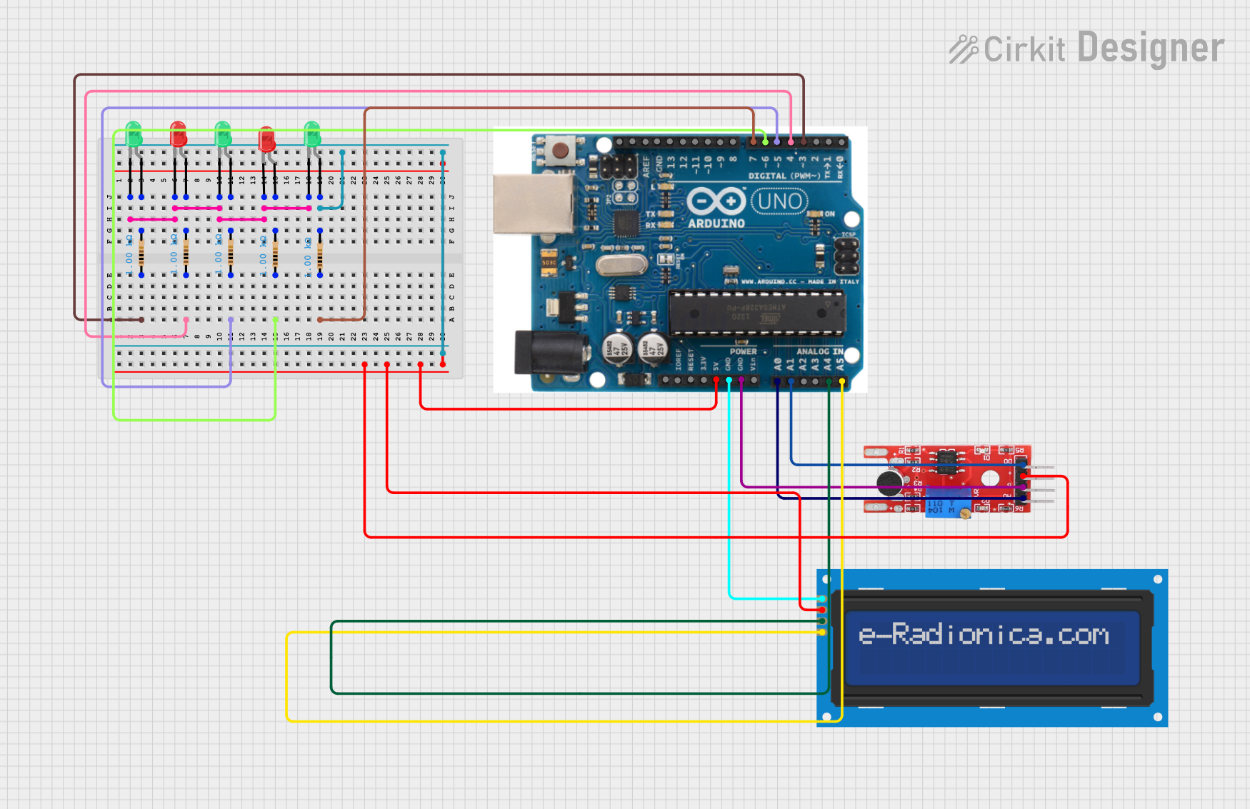
This circuit is designed to display lyrics on an LCD screen and flash LEDs in response to sound levels detected by a microphone sensor. The circuit uses an Arduino UNO microcontroller to control the components, which include a KY-038 microphone sensor, an LCD screen, and multiple LEDs with resistors.
Component List
KY-038 Microphone Sensor
- Pins: +, G, A0, D0
- Description: Detects sound levels and outputs analog and digital signals.
LCD Screen 16x2 I2C
- Pins: SCL, SDA, VCC, GND
- Description: Displays text on a 16x2 character screen using I2C communication.
Arduino UNO
- Pins: SDA, AREF, GND, 13, 12, 11, 10, 9, 8, 7, 6, 5, 4, 3, 2, 1, 0, A5, A4, A3, A2, A1, A0, Vin, 5V, 3.3V, RESET, IOREF, SCL
- Description: Microcontroller used to control the circuit.
LED: Two Pin (Red)
- Pins: Cathode, Anode
- Description: Red LED used for visual indication.
LED: Two Pin (Green)
- Pins: Cathode, Anode
- Description: Green LED used for visual indication.
Resistor
- Pins: Pin1, Pin2
- Description: Limits current to the LEDs.
- Properties: 1000 Ohms
Wiring Details
KY-038 Microphone Sensor
- + connected to 5V on Arduino UNO
- G connected to GND on Arduino UNO
- A0 connected to A0 on Arduino UNO
- D0 connected to A1 on Arduino UNO
LCD Screen 16x2 I2C
- SCL connected to A5 on Arduino UNO
- SDA connected to A4 on Arduino UNO
- VCC connected to 5V on Arduino UNO
- GND connected to GND on Arduino UNO
Arduino UNO
- Pin 3 connected to Pin1 of a Resistor
- Pin 4 connected to Pin1 of a Resistor
- Pin 5 connected to Pin1 of a Resistor
- Pin 6 connected to Pin1 of a Resistor
- Pin 7 connected to Pin1 of a Resistor
- GND connected to G of KY-038 and GND of LCD screen
LED: Two Pin (Red)
- Cathode connected to common cathode net
- Anode connected to Pin2 of a Resistor
LED: Two Pin (Green)
- Cathode connected to common cathode net
- Anode connected to Pin2 of a Resistor
Resistor
- Pin1 connected to respective Arduino UNO pins (3, 4, 5, 6, 7)
- Pin2 connected to respective LED anodes
Documented Code
#include <LiquidCrystal_I2C.h>

// Pin definitions
int soundPin = A0;
int LED1 = 3;
int LED2 = 4;
int LED3 = 5;
int LED4 = 6;
int LED5 = 7;
int LED6 = 8;
int LED7 = 9;
int LED8 = 10;

// LCD setup (I2C address 0x27, 16 columns, 2 rows)
LiquidCrystal_I2C lcd(0x27, 16, 2);

// Full lyrics of "Roses" by The Chainsmokers (with manual timing)
const String lyrics[] = {
  "BSINFO2E PROJECT", //line 1
  "Taking it slow", //line 2
  "but its not typical", //line 3
  "He already knows that my love is", //line 4
  "fire", //line 5
  "His heart was a stone", //line 6
  "but then his hands roamed", //line 7
  "I turned him to gold ", // line 8
  "and took him higher", //line 9
  "Well, I'll be your daydream,", //line 10
  "I'll be your favorite things", //line 11
  "We could be beautiful", //line 12
  "Get drunk on the good life", //line 13
  "I'll take you to paradise", //line 14
  "Say you'll never let me go", //line 15