
Circuit Documentation
Summary
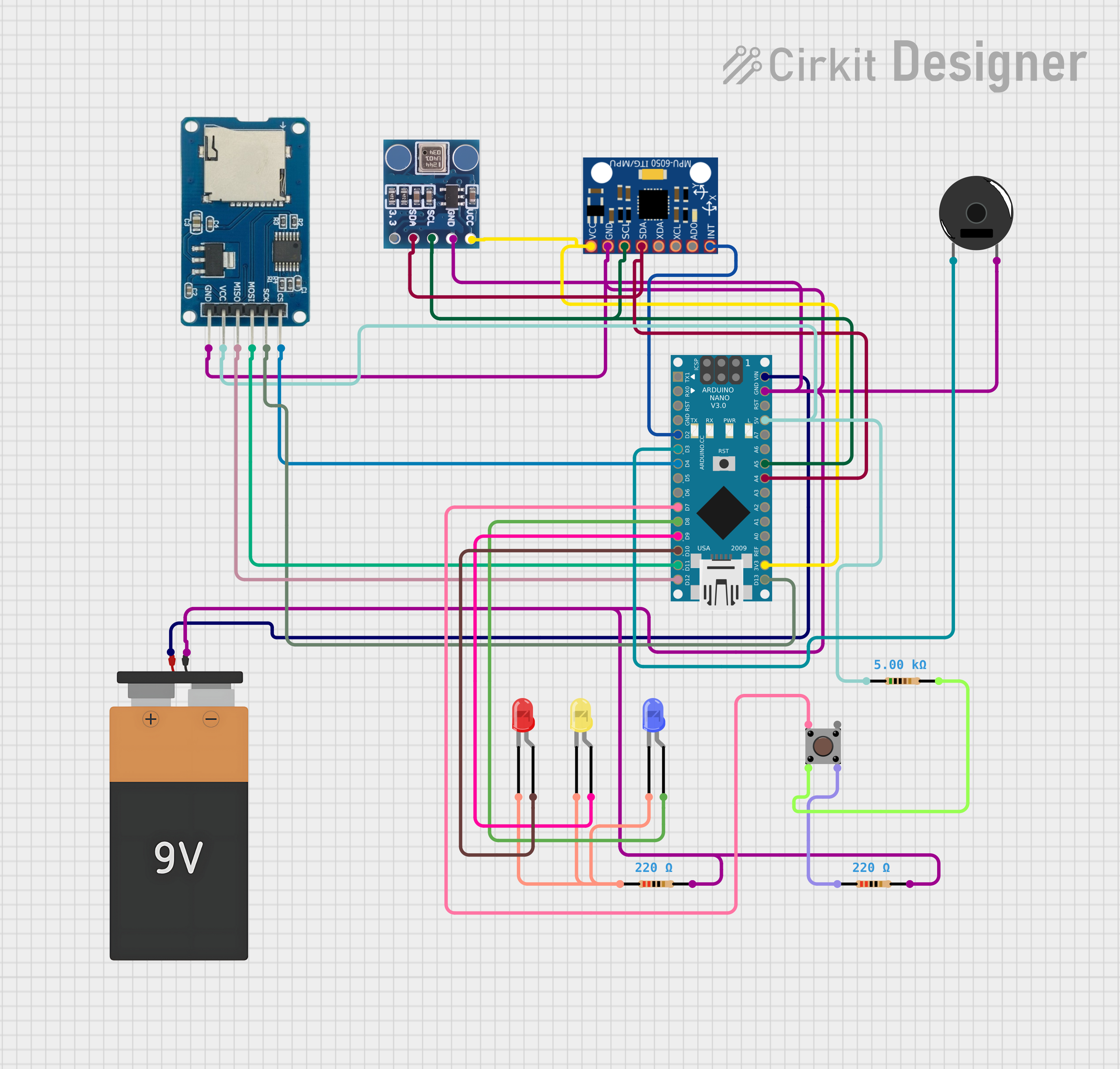
This circuit integrates various components including sensors (BMP180, MPU-6050), an Arduino Nano microcontroller, LEDs of different colors (red, yellow, blue), a pushbutton, resistors, a piezo buzzer, a micro SD card module, and a 9V battery. The circuit is designed to interface sensors with the Arduino Nano for data acquisition, provide visual indicators through LEDs, receive user input via a pushbutton, and store data on a micro SD card. The piezo buzzer can be used for audio feedback. Power is supplied by the 9V battery, regulated to the required voltages for different components.
Component List
- BMP180: A digital barometric pressure sensor.
- Arduino Nano: A small, complete, and breadboard-friendly microcontroller board based on the ATmega328P.
- MPU-6050: A 6-axis motion tracking device that combines a 3-axis gyroscope and a 3-axis accelerometer.
- LED (Red, Yellow, Blue): Light Emitting Diodes used as visual indicators.
- Pushbutton: A simple switch mechanism for controlling some aspect of a machine or a process.
- Resistors: Electrical components that implement electrical resistance as a circuit element.
- Piezo Buzzer: An electronic device that produces a tone, alarm, or sound when electric power is applied.
- Battery 9V: A standard 9-volt battery to provide power to the circuit.
- Micro SD Card Module: A module that allows micro SD cards to be read from and written to by a microcontroller.
Wiring Details
BMP180
- SDA connected to Arduino Nano A4 (SDA)
- SCL connected to Arduino Nano A5 (SCL)
- GND connected to common ground net
- VCC connected to Arduino Nano 3V3
Arduino Nano
- D2 connected to MPU-6050 INT
- D3 connected to Piezo Buzzer pin 1
- D4 connected to Micro SD Card Module cs
- D7 connected to Pushbutton Pin 1 (in)
- D8 connected to LED (Blue) anode
- D9 connected to LED (Yellow) anode
- D10 connected to LED (Red) anode
- D11/MOSI connected to Micro SD Card Module mosi
- D12/MISO connected to Micro SD Card Module miso
- D13/SCK connected to Micro SD Card Module sck
- GND connected to common ground net
- VIN connected to Battery 9V VCC
- 3V3 connected to BMP180 VCC and MPU-6050 VCC
- 5V connected to Micro SD Card Module vcc via a 5kΩ resistor
MPU-6050
- SDA connected to Arduino Nano A4 (SDA)
- SCL connected to Arduino Nano A5 (SCL)
- GND connected to common ground net
- VCC connected to Arduino Nano 3V3
- INT connected to Arduino Nano D2
LEDs (Red, Yellow, Blue)
- Anode (Red) connected to Arduino Nano D10
- Anode (Yellow) connected to Arduino Nano D9
- Anode (Blue) connected to Arduino Nano D8
- Cathode (All) connected to common ground net via a 220Ω resistor
Pushbutton
- Pin 1 (in) connected to Arduino Nano D7
- Pin 2 (in) connected to one end of a 5kΩ resistor
- Pin 3 (out) not connected
- Pin 4 (out) connected to one end of a 220Ω resistor
Resistors
- 220Ω connected between LED cathodes and common ground net
- 5kΩ connected between Pushbutton Pin 2 (in) and Micro SD Card Module vcc
- 5kΩ connected between Micro SD Card Module vcc and Arduino Nano 5V
Piezo Buzzer
- Pin 1 connected to Arduino Nano D3
- Pin 2 connected to common ground net
Micro SD Card Module
- cs connected to Arduino Nano D4
- sck connected to Arduino Nano D13/SCK
- mosi connected to Arduino Nano D11/MOSI
- miso connected to Arduino Nano D12/MISO
- vcc connected to Arduino Nano 5V via a 5kΩ resistor
- gnd connected to common ground net
Battery 9V
- VCC connected to Arduino Nano VIN
- GND connected to common ground net
Documented Code
Arduino Nano Code (sketch.ino)
void setup() {
  // put your setup code here, to run once:

}

void loop() {
  // put your main code here, to run repeatedly:

}
Note: The provided code is a template and does not contain any functional code. It needs to be populated with the setup and loop functions to control the circuit components as per the requirements.