
Circuit Documentation
Summary
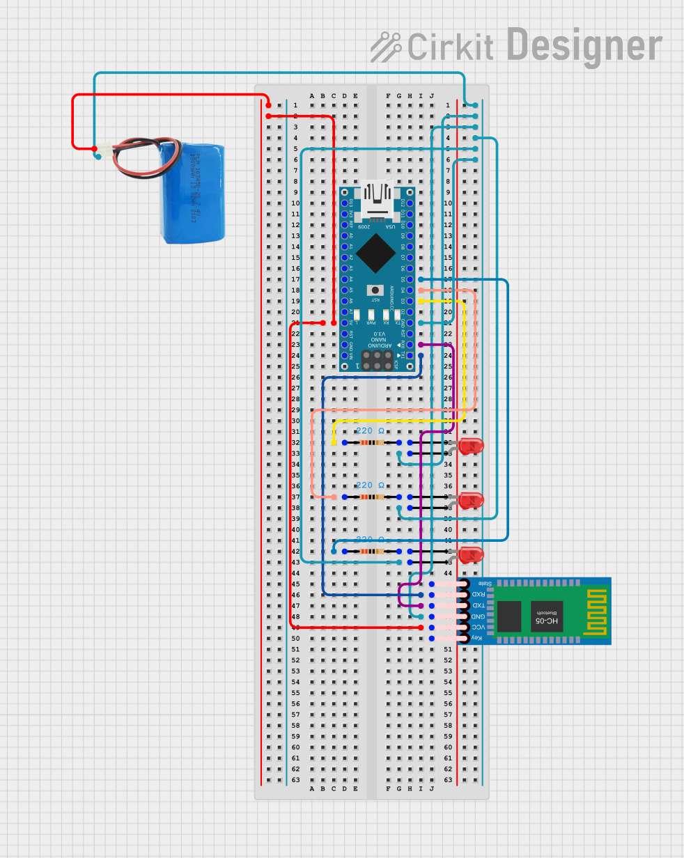
This circuit integrates an Arduino Nano microcontroller with a HC-05 Bluetooth module, three LEDs with corresponding resistors, and a 5V battery. The Arduino Nano is used as the central processing unit, controlling the LEDs and communicating with the HC-05 Bluetooth module. The HC-05 module enables wireless communication, potentially with a smartphone or computer. Each LED is connected in series with a 220-ohm resistor to limit the current and prevent damage to the LEDs. The 5V battery provides power to the circuit.
Component List
Arduino Nano
- Microcontroller board based on the ATmega328P
- It has a variety of digital and analog I/O pins.
Resistor (220 Ohms)
- Three resistors are used in the circuit, each with a resistance of 220 Ohms.
- They are used to limit the current through the LEDs.
LED: Two Pin (Red)
- Three red LEDs are used as visual indicators.
- Each LED has an anode and a cathode pin.
HC-05 Bluetooth Module
- A wireless communication module that allows for Bluetooth connectivity.
- It has pins for power (VCC, GND), communication (TXD, RXD), and state indication.
5V Battery
- Provides the power supply for the circuit.
- It has a positive and a negative terminal.
Wiring Details
Arduino Nano
- Digital Pin D5: Connected to a 220-ohm resistor leading to an LED.
- Digital Pin D4: Connected to a 220-ohm resistor leading to another LED.
- Digital Pin D3: Connected to a 220-ohm resistor leading to the third LED.
- 5V Pin: Supplies power to the HC-05 Bluetooth module and is connected to the positive terminal of the 5V battery.
- GND Pin: Common ground for the circuit, connected to the anodes of all LEDs, the GND pin of the HC-05 Bluetooth module, and the negative terminal of the 5V battery.
- Digital Pin D0/RX: Receives data from the TXD pin of the HC-05 Bluetooth module.
- Digital Pin D1/TX: Transmits data to the RXD pin of the HC-05 Bluetooth module.
Resistor (220 Ohms)
- One side of each resistor is connected to a digital pin on the Arduino Nano (D5, D4, D3).
- The other side of each resistor is connected to the cathode of an LED.
LED: Two Pin (Red)
- The anode of each LED is connected to the common ground.
- The cathode of each LED is connected to a 220-ohm resistor.
HC-05 Bluetooth Module
- VCC: Connected to the 5V output from the Arduino Nano and the positive terminal of the 5V battery.
- GND: Connected to the common ground.
- TXD: Transmits data to the RX pin (D0) of the Arduino Nano.
- RXD: Receives data from the TX pin (D1) of the Arduino Nano.
5V Battery
- Positive Terminal: Connected to the 5V pin of the Arduino Nano and the VCC pin of the HC-05 Bluetooth module.
- Negative Terminal: Connected to the common ground.
Documented Code
Arduino Nano - sketch.ino
void setup() {
  // put your setup code here, to run once:

}

void loop() {
  // put your main code here, to run repeatedly:

}
Arduino Nano - documentation.txt
(No additional documentation provided for the code)
This document provides an overview of the circuit components, their wiring, and the basic structure of the embedded code. Further details, such as the functionality of the code and the specific behavior of the LEDs, would require additional information.