
Circuit Documentation
Summary of the Circuit
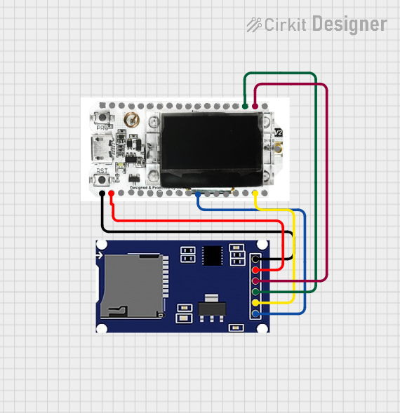
This circuit integrates an SD card module with a Heltec LoRa V2 microcontroller board. The SD card module is interfaced with the Heltec LoRa V2 via SPI (Serial Peripheral Interface) for data storage and retrieval. The VCC and GND pins provide the necessary power connections. This setup could be used for applications that require remote data logging and wireless communication.
Component List
SD Card Module
- Pins: CS, SCK, MOSI, MISO, VCC, GND
- Description: A module that allows an SD card to be interfaced with a microcontroller over SPI for data storage.
- Purpose: To provide data storage capabilities to the circuit.
Heltec LoRa V2
- Pins: GND, 5V, Vext, RX, TX, RST, 0, 22, 19, 23, 18, 5, 15, 2, 4, 17, 16, 21, 13, 12, 14, 27, 26, 25, 33, 32, 35, 34, 39, 38, 37, 36, 3.3V, ANT
- Description: A microcontroller board with built-in LoRa (Long Range) wireless communication capabilities.
- Purpose: To control the SD module and handle wireless data transmission.
Wiring Details
SD Card Module Wiring
- CS - Connected to Heltec LoRa V2 pin 23
- SCK - Connected to Heltec LoRa V2 pin 17
- MOSI - Connected to Heltec LoRa V2 pin 12
- MISO - Connected to Heltec LoRa V2 pin 13
- VCC - Connected to Heltec LoRa V2 pin 5V
- GND - Connected to Heltec LoRa V2 pin GND
Heltec LoRa V2 Wiring
- Pin 23 - Connected to SD module CS
- Pin 17 - Connected to SD module SCK
- Pin 12 - Connected to SD module MOSI
- Pin 13 - Connected to SD module MISO
- Pin 5V - Connected to SD module VCC
- Pin GND - Connected to SD module GND
Documented Code
No code has been provided for the microcontrollers in the circuit. When code is available, it should be documented in this section with explanations of how the code interacts with the hardware, any libraries used, and the functionality it provides.