
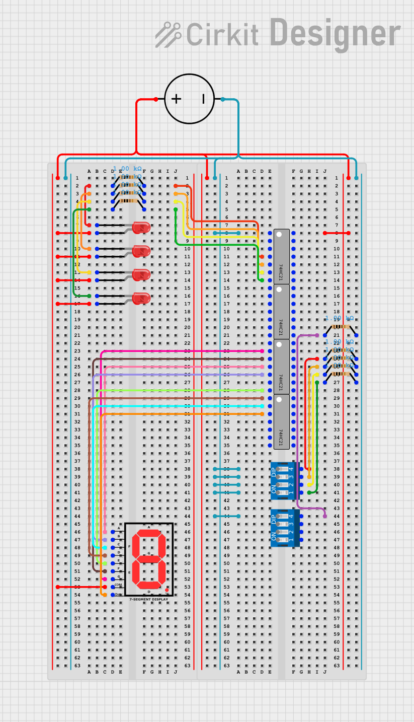
Circuit Documentation
Summary
This circuit consists of a DC power source, multiple resistors, red LEDs, a 7-segment display, 74HC21 logic gates, and DIP switches. The circuit is designed to control the LEDs and the 7-segment display using the 74HC21 logic gates and DIP switches.
Component List
DC Power Source
- Description: Provides the necessary voltage and current to power the circuit.
- Pins: Ground, Positive
Resistor
- Description: Limits the current flowing through the circuit.
- Pins: pin1, pin2
- Properties:
- Resistance: 1000 Ohms
LED: Two Pin (red)
- Description: Emits light when current flows through it.
- Pins: cathode, anode
7-segment Display
- Description: Displays numerical digits using seven individual segments.
- Pins: A, B, C, D, E, F, G, COM, dot
74HC21
- Description: Dual 4-input AND gate.
- Pins: A1, B1, NC, C1, D1, Y1, GND, VCC, D2, C2, B2, A2, Y2
DIP Switch 4 Position
- Description: Provides a way to manually set binary inputs.
- Pins: 1, 2, 3, 4, 5, 6, 7, 8
Wiring Details
DC Power Source
- Ground: Connected to:
- 74HC21 (A1)
- Resistor (pin2)
- Positive: Connected to:
- LED (anode)
- 7-segment Display (COM)
- 74HC21 (VCC)
Resistor
Resistor 1:
- pin1: Connected to LED (cathode)
- pin2: Connected to 74HC21 (C1)
Resistor 2:
- pin1: Connected to LED (cathode)
- pin2: Connected to 74HC21 (D1)
Resistor 3:
- pin1: Connected to LED (cathode)
- pin2: Connected to 74HC21 (Y1)
Resistor 4:
- pin1: Connected to LED (cathode)
- pin2: Connected to 74HC21 (GND)
Resistor 5:
- pin1: Connected to 74HC21 (Y2)
- pin2: Connected to DIP Switch (4)
Resistor 6:
- pin1: Connected to 74HC21 (C2)
- pin2: Connected to DIP Switch (4)
Resistor 7:
- pin1: Connected to 74HC21 (NC)
- pin2: Connected to DIP Switch (3)
Resistor 8:
- pin1: Connected to 74HC21 (B2)
- pin2: Connected to DIP Switch (2)
Resistor 9:
- pin1: Connected to 74HC21 (A2)
- pin2: Connected to DIP Switch (1)
LED: Two Pin (red)
LED 1:
- cathode: Connected to Resistor (pin1)
- anode: Connected to DC Power Source (Positive)
LED 2:
- cathode: Connected to Resistor (pin1)
- anode: Connected to DC Power Source (Positive)
LED 3:
- cathode: Connected to Resistor (pin1)
- anode: Connected to DC Power Source (Positive)
LED 4:
- cathode: Connected to Resistor (pin1)
- anode: Connected to DC Power Source (Positive)
7-segment Display
- A: Connected to 74HC21 (C1)
- B: Connected to 74HC21 (D1)
- C: Connected to 74HC21 (B1)
- D: Connected to 74HC21 (A1)
- E: Connected to 74HC21 (GND)
- F: Connected to 74HC21 (NC)
- G: Connected to 74HC21 (B1)
- COM: Connected to DC Power Source (Positive)
- dot: Connected to 74HC21 (NC)
74HC21
- A1: Connected to DC Power Source (Ground)
- B1: Connected to 7-segment Display (C)
- C1: Connected to Resistor (pin2)
- D1: Connected to Resistor (pin2)
- Y1: Connected to Resistor (pin2)
- GND: Connected to Resistor (pin2)
- VCC: Connected to DC Power Source (Positive)
- D2: Not connected
- C2: Connected to Resistor (pin1)
- B2: Connected to Resistor (pin1)
- A2: Connected to Resistor (pin1)
- Y2: Connected to Resistor (pin1)
DIP Switch 4 Position
- 1: Connected to Resistor (pin1)
- 2: Connected to Resistor (pin1)
- 3: Connected to Resistor (pin1)
- 4: Connected to Resistor (pin1)
- 5: Not connected
- 6: Not connected
- 7: Not connected
- 8: Not connected
Code
No code is provided for this circuit.