
Arduino UNO Based GPS Tracker with Ultrasonic Distance Measurement and GSM Reporting
View and Edit Project In Cirkit Designer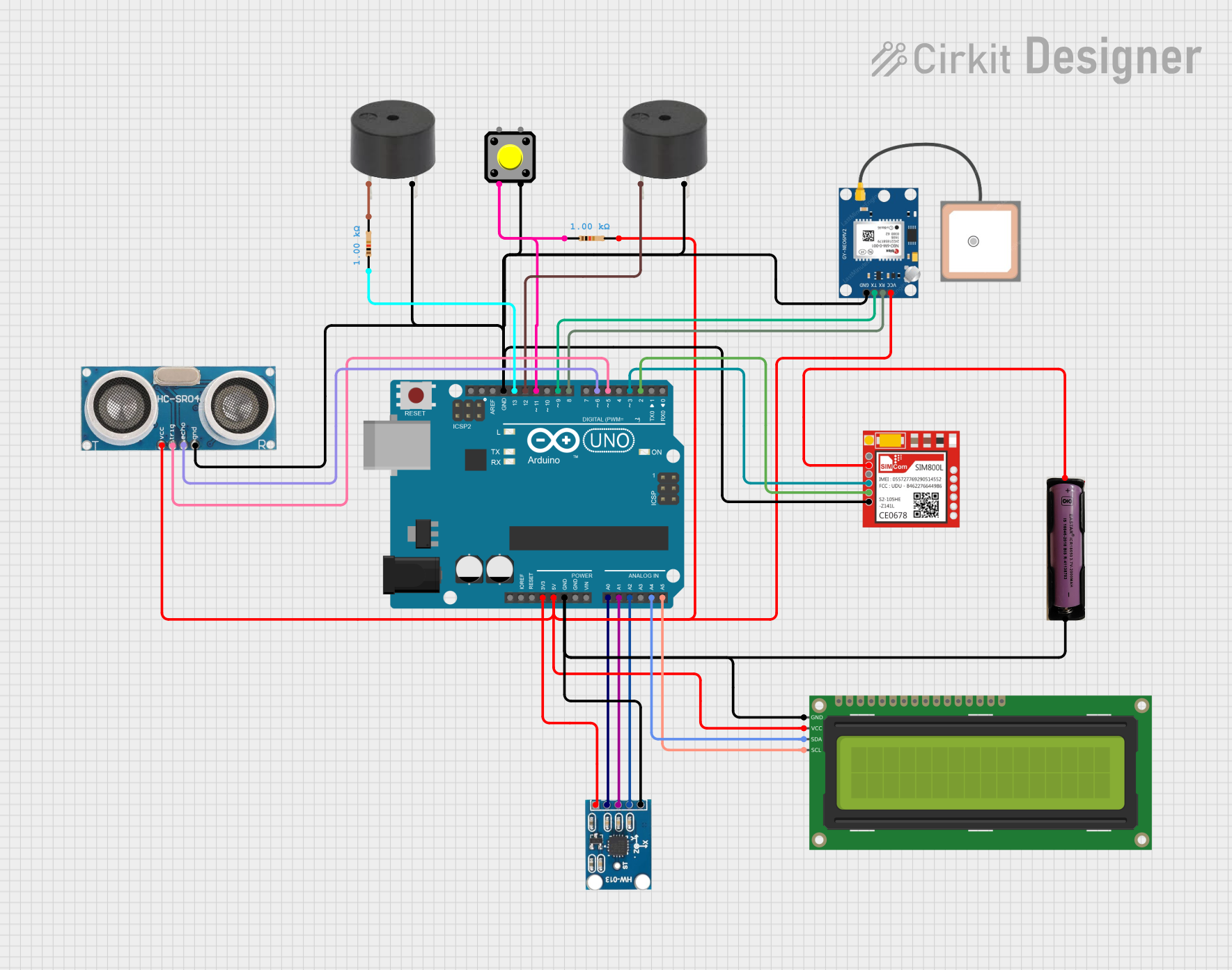
Circuit Documentation
Summary
This circuit integrates various components with an Arduino UNO microcontroller to form a complex system capable of interfacing with sensors, a display, a communication module, and user input devices. The system is designed to collect data from a GPS module and an accelerometer, display information on an LCD, and communicate via the SIM800L GSM module. It also includes a buzzer for audio feedback and a pushbutton for user interaction. The circuit is powered by a 3.7V power source.
Component List
Arduino UNO
- Microcontroller board based on the ATmega328P
- It has 14 digital input/output pins, 6 analog inputs, a 16 MHz quartz crystal, a USB connection, a power jack, an ICSP header, and a reset button.
Resistor (1k Ohm)
- Two resistors with a resistance of 1000 Ohms each
- Used for current limiting or voltage division
SIM800L
- GSM/GPRS module
- Capable of making calls, sending messages, and accessing the internet
GPS NEO 6M
- GPS module
- Provides location data
Buzzer
- Audio signaling device
- Two buzzers are used for generating sound
AITrip ADXL335 GY-61 (Accelerometer)
- Analog accelerometer
- Measures acceleration in three axes (X, Y, Z)
Pushbutton
- A simple switch mechanism for controlling some aspect of a machine or a process
16x2 I2C LCD
- Alphanumeric Liquid Crystal Display
- Displays 16 characters per line in 2 lines
- Uses I2C communication protocol
Ultrasonic Sensor
- Measures distance by emitting ultrasonic waves and measuring the time taken for the echo to return
3.7V Power Source
- Provides power to the circuit
Wiring Details
Arduino UNO
3.3Vconnected to AITrip ADXL335 GY-61 VCC5Vconnected to 16x2 I2C LCD VCC, Ultrasonic Sensor VCC, GPS NEO 6M VCC, and one terminal of a 1k Ohm resistorGNDconnected to common ground netA0connected to AITrip ADXL335 GY-61 X-OutA1connected to AITrip ADXL335 GY-61 Y-OutA2connected to AITrip ADXL335 GY-61 Z-OutA4connected to 16x2 I2C LCD SDAA5connected to 16x2 I2C LCD SCLD2connected to SIM800L TXDD3connected to SIM800L RXDD5connected to Ultrasonic Sensor TriggerD6connected to Ultrasonic Sensor EchoD8connected to GPS NEO 6M RXD9connected to GPS NEO 6M TXD11connected to one terminal of a 1k Ohm resistor, which is connected to a pushbuttonD12connected to one buzzer PIND13connected to one terminal of a 1k Ohm resistor, which is connected to the other buzzer PIN
Resistor (1k Ohm)
- One terminal connected to Arduino UNO 5V
- Other terminal connected to 16x2 I2C LCD VCC, Ultrasonic Sensor VCC, GPS NEO 6M VCC
SIM800L
VCCconnected to 3.7V power source +GNDconnected to common ground netRXDconnected to Arduino UNO D3TXDconnected to Arduino UNO D2
GPS NEO 6M
VCCconnected to one terminal of a 1k Ohm resistorGNDconnected to common ground netRXconnected to Arduino UNO D8TXconnected to Arduino UNO D9
Buzzer
PINconnected to Arduino UNO D12 (first buzzer) and D13 via a 1k Ohm resistor (second buzzer)GNDconnected to common ground net
AITrip ADXL335 GY-61 (Accelerometer)
VCCconnected to Arduino UNO 3.3VGNDconnected to common ground netX-Outconnected to Arduino UNO A0Y-Outconnected to Arduino UNO A1Z-Outconnected to Arduino UNO A2
Pushbutton
- One terminal connected to Arduino UNO D11 via a 1k Ohm resistor
- Another terminal connected to common ground net
16x2 I2C LCD
VCCconnected to one terminal of a 1k Ohm resistorGNDconnected to common ground netSDAconnected to Arduino UNO A4SCLconnected to Arduino UNO A5
Ultrasonic Sensor
+VCCconnected to one terminal of a 1k Ohm resistorGNDconnected to common ground netTriggerconnected to Arduino UNO D5Echoconnected to Arduino UNO D6
3.7V Power Source
+connected to SIM800L VCC-connected to common ground net
Documented Code
Arduino UNO Code (sketch.ino)
void setup() {
  // put your setup code here, to run once:

}

void loop() {
  // put your main code here, to run repeatedly:

}
Note: The provided code is a template and does not include any functional code. It needs to be populated with the logic to control and interact with the connected components based on the requirements of the project.