
Circuit Documentation
Summary
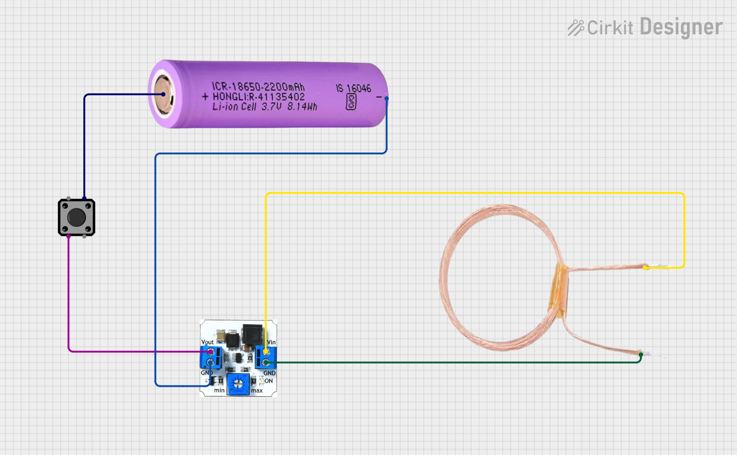
This document provides a detailed overview of a circuit consisting of a tactile switch, a copper coil, a battery, and a DC/DC booster. The circuit is designed to boost the voltage from the battery and control the output using a tactile switch.
Component List
Tactile Switch Buttons - 12mm Square
- Description: A 12mm square tactile switch used for user input.
- Pins: 3, 1, 4, 2
COPPER COIL - 30 TURNS
- Description: A copper coil with 30 turns used for inductance in the circuit.
- Pins: 1 PIN, 2 PIN
Battery 18650
- Description: A rechargeable lithium-ion battery.
- Pins: +, -
DC/DC booster
- Description: A DC/DC booster used to increase the voltage from the battery.
- Pins: GND, Vin, Vout
Wiring Details
Tactile Switch Buttons - 12mm Square
- Pin 3 is connected to Vout of the DC/DC booster.
- Pin 2 is connected to + of the Battery 18650.
COPPER COIL - 30 TURNS
- Pin 1 PIN is connected to Vin of the DC/DC booster.
- Pin 2 PIN is connected to GND of the DC/DC booster.
Battery 18650
- Pin + is connected to Pin 2 of the Tactile Switch Buttons - 12mm Square.
- Pin - is connected to GND of the DC/DC booster.
DC/DC booster
- Pin Vout is connected to Pin 3 of the Tactile Switch Buttons - 12mm Square.
- Pin Vin is connected to Pin 1 PIN of the COPPER COIL - 30 TURNS.
- Pin GND is connected to Pin 2 PIN of the COPPER COIL - 30 TURNS and Pin - of the Battery 18650.
Code
There is no microcontroller code provided for this circuit.