
Circuit Documentation
Summary of the Circuit
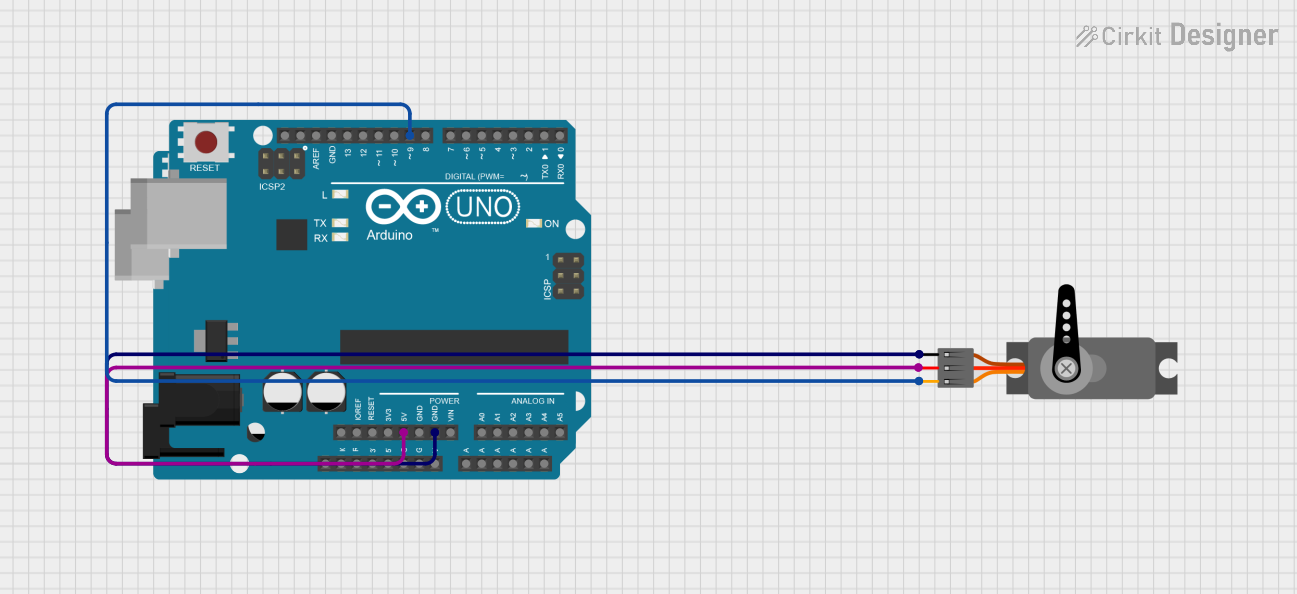
This circuit consists of three Arduino UNO microcontroller boards and one servo motor. The servo is controlled by one of the Arduino UNO boards, which sends PWM (Pulse Width Modulation) signals to the servo to control its position. The servo is powered by the 5V output from the same Arduino UNO. The other two Arduino UNO boards are present in the circuit but do not have any specified functionality in the provided documentation.
Component List
Arduino UNO
- Description: A microcontroller board based on the ATmega328P. It has 14 digital input/output pins, 6 analog inputs, a 16 MHz quartz crystal, a USB connection, a power jack, an ICSP header, and a reset button.
- Purpose: To control the servo motor and potentially other peripherals or sensors in the circuit.
Servo
- Description: An actuator that can be precisely controlled for angular or linear position, velocity, and acceleration.
- Purpose: To perform mechanical actions as instructed by the controlling Arduino UNO.
Wiring Details
Arduino UNO (Controlling the Servo)
- 5V to Servo VCC (Power supply for the servo)
- GND to Servo GND (Common ground reference)
- D9 to Servo PWM (PWM signal to control the servo position)
Arduino UNO (Other Boards)
- No specific wiring details provided. These boards are not connected in the circuit as per the provided net list.
Documented Code
Code for Arduino UNO (Controlling the Servo)
#include<Servo.h>
Servo s1;

void setup() {
  s1.attach(9); // Attaches the servo on pin 9 to the servo object
}

void loop() {
  // Rotates the servo to 90 degrees
  s1.write(90);
  delay(1000); // Waits for 1 second
  // Rotates the servo to 180 degrees
  s1.write(180);
  delay(1000); // Waits for 1 second
}
File: sketch.ino
Code for Other Arduino UNO Boards
The other two Arduino UNO boards have no specific code provided that would indicate their purpose in the circuit. They contain empty setup and loop functions, which are the default structure for an Arduino sketch.
void setup() {
  // put your setup code here, to run once:
}

void loop() {
  // put your main code here, to run repeatedly:
}
File: sketch.ino for both of the other Arduino UNO boards
This concludes the documentation for the provided circuit. The circuit is designed to control a servo motor using one of the Arduino UNO boards, while the role of the other two Arduino UNO boards remains undefined without further information.