
Circuit Documentation
Summary of the Circuit
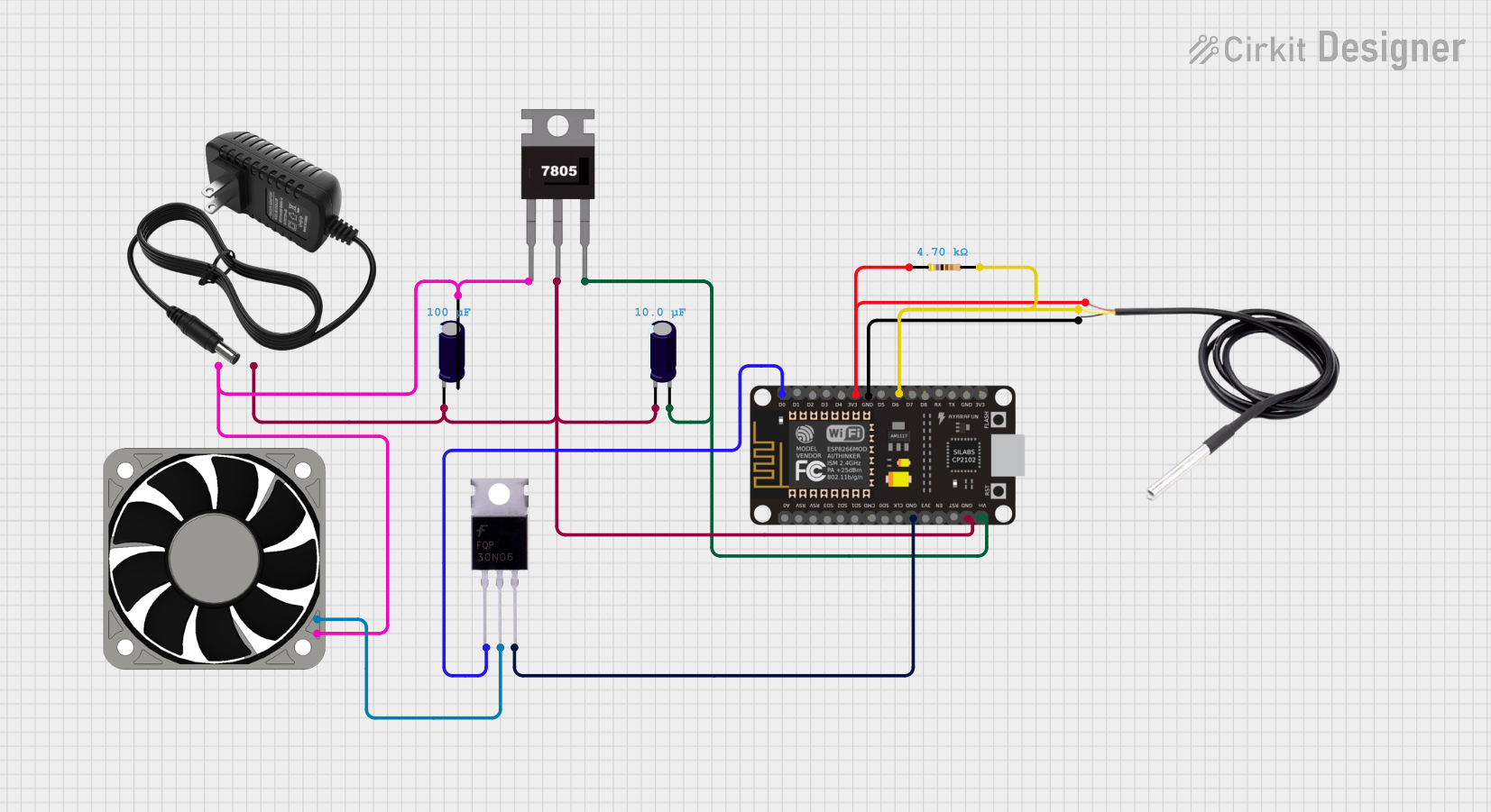
This circuit appears to be designed to control a 12V fan using an ESP8266 NodeMCU microcontroller. The ESP8266 is powered by a 7805 voltage regulator, which steps down the voltage from a 12V power supply to 5V required by the microcontroller. The circuit also includes a DS18B20 temperature sensor for measuring temperature, which may be used to control the fan speed. A MOSFET is used as a switch to control the power to the fan, and it is driven by one of the GPIO pins of the ESP8266. Capacitors are included for voltage smoothing and stability.
Component List
7805 Voltage Regulator
- Pins: Vin, Gnd, Vout
- Description: A voltage regulator that outputs a steady 5V from a higher voltage input.
Electrolytic Capacitor (0.0001 Farads)
- Pins: -, +
- Description: Used for voltage smoothing on the input or output of the voltage regulator.
ESP8266 NodeMCU
- Pins: D0-D8, RX, TX, A0, RSV, SD3, SD2, SD1, CMD, SD0, CLK, EN, RST, VIN, 3V3, GND
- Description: A microcontroller with WiFi capability, used for controlling the circuit's logic.
DS18B20 Temperature Sensor
- Pins: Signal, GND, Vcc
- Description: A digital temperature sensor used for measuring temperature.
Resistor (4700 Ohms)
- Pins: Pin1, Pin2
- Description: A resistor, possibly used as a pull-up for the temperature sensor.
MOSFET
- Pins: Gate, Drain, Source
- Description: A type of transistor used to switch the fan on and off.
40mm Fan 12V
- Pins: +12V, -12V
- Description: A 12V fan for cooling.
12V Power Supply
- Pins: +, -
- Description: Provides the power for the circuit.
Electrolytic Capacitor (0.00001 Farads)
- Pins: -, +
- Description: Another capacitor for voltage smoothing, likely on the output of the voltage regulator.
Wiring Details
7805 Voltage Regulator
- Vin connected to the +12V of the 12V power supply and the + pin of the 0.0001 Farads Electrolytic Capacitor.
- Gnd connected to the ground net, which includes the GND pins of the ESP8266, DS18B20, and both Electrolytic Capacitors, as well as the - pin of the 12V power supply.
- Vout connected to the + pin of the 0.00001 Farads Electrolytic Capacitor and the VIN pin of the ESP8266.
Electrolytic Capacitor (0.0001 Farads)
- - connected to the ground net.
- + connected to the Vin pin of the 7805 Voltage Regulator.
ESP8266 NodeMCU
- D0 connected to the Gate pin of the MOSFET.
- 3V3 connected to the Vcc pin of the DS18B20 and pin1 of the Resistor.
- GND connected to the ground net.
- D6 connected to the signal pin of the DS18B20 and pin2 of the Resistor.
- VIN connected to the Vout pin of the 7805 Voltage Regulator.
DS18B20 Temperature Sensor
- Signal connected to the D6 pin of the ESP8266 and pin2 of the Resistor.
- GND connected to the ground net.
- Vcc connected to the 3V3 pin of the ESP8266 and pin1 of the Resistor.
Resistor (4700 Ohms)
- Pin1 connected to the 3V3 pin of the ESP8266 and the Vcc pin of the DS18B20.
- Pin2 connected to the signal pin of the DS18B20 and the D6 pin of the ESP8266.
MOSFET
- Gate connected to the D0 pin of the ESP8266.
- Drain connected to the -12V pin of the 40mm Fan 12V.
- Source connected to the ground net.
40mm Fan 12V
- +12V connected to the + pin of the 12V power supply and the + pin of the 0.0001 Farads Electrolytic Capacitor.
- -12V connected to the Drain pin of the MOSFET.
12V Power Supply
- + connected to the Vin pin of the 7805 Voltage Regulator and the +12V pin of the 40mm Fan 12V.
- - connected to the ground net.
Electrolytic Capacitor (0.00001 Farads)
- - connected to the ground net.
- + connected to the Vout pin of the 7805 Voltage Regulator.
Documented Code
There is no code provided for the microcontroller. The expected code would likely involve initializing the GPIO pins, setting up the WiFi connection (if needed), reading the temperature from the DS18B20 sensor, and controlling the MOSFET gate to turn the fan on or off based on the temperature readings.