Cirkit Designer
Your all-in-one circuit design IDE
Home /
Project Documentation
Arduino UNO-Based Turbidity Sensor with LCD Display
Circuit Documentation
Summary
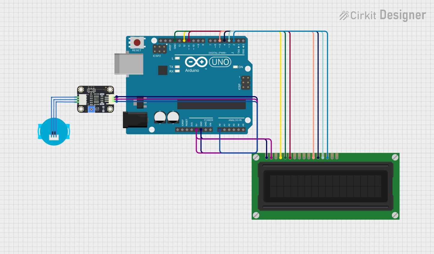
This circuit involves an Arduino UNO microcontroller, a turbidity sensor, and an LCD display. The Arduino UNO serves as the central controller, reading data from the turbidity sensor and displaying the information on the LCD display.
Component List
Arduino UNO
- Description: A microcontroller board based on the ATmega328P.
- Pins: UNUSED, IOREF, Reset, 3.3V, 5V, GND, Vin, A0, A1, A2, A3, A4, A5, SCL, SDA, AREF, D13, D12, D11, D10, D9, D8, D7, D6, D5, D4, D3, D2, D1, D0
Turbidity Sensor
- Description: A sensor used to measure the turbidity (cloudiness) of water.
- Pins: OUT, VCC, GND
LCD Display (16 pin)
- Description: A 16-pin LCD display used to show data.
- Pins: VSS, VDD, VO, RS, R_W, E, DB0, DB1, DB2, DB3, DB4, DB5, DB6, DB7, A, K
Wiring Details
Arduino UNO
- 5V: Connected to VCC of the Turbidity Sensor and VDD of the LCD Display.
- GND: Connected to GND of the Turbidity Sensor, VSS of the LCD Display, and R_W of the LCD Display.
- A0: Connected to OUT of the Turbidity Sensor.
- D12: Connected to RS of the LCD Display.
- D11: Connected to E of the LCD Display.
- D5: Connected to DB4 of the LCD Display.
- D4: Connected to DB5 of the LCD Display.
- D3: Connected to DB6 of the LCD Display.
- D2: Connected to DB7 of the LCD Display.
Turbidity Sensor
- VCC: Connected to 5V of the Arduino UNO and VDD of the LCD Display.
- GND: Connected to GND of the Arduino UNO and VSS of the LCD Display.
- OUT: Connected to A0 of the Arduino UNO.
LCD Display (16 pin)
- VDD: Connected to 5V of the Arduino UNO and VCC of the Turbidity Sensor.
- VSS: Connected to GND of the Arduino UNO and GND of the Turbidity Sensor.
- RS: Connected to D12 of the Arduino UNO.
- R_W: Connected to GND of the Arduino UNO.
- E: Connected to D11 of the Arduino UNO.
- DB4: Connected to D5 of the Arduino UNO.
- DB5: Connected to D4 of the Arduino UNO.
- DB6: Connected to D3 of the Arduino UNO.
- DB7: Connected to D2 of the Arduino UNO.
Documented Code
sketch.ino
void setup() {
  // put your setup code here, to run once:

}

void loop() {
  // put your main code here, to run repeatedly:

}
documentation.txt