Arduino-Controlled Robotic Vehicle with Ultrasonic Sensor and IR Communication
Circuit Documentation
Summary
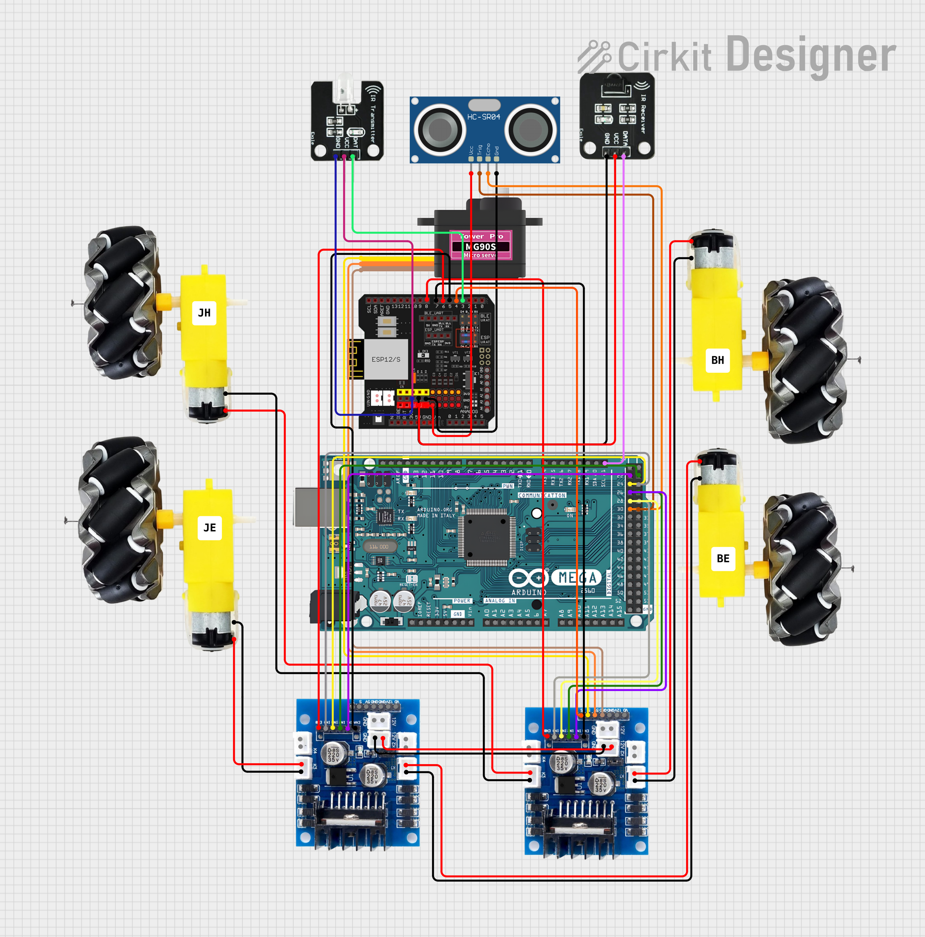
This document provides a detailed overview of a circuit designed to control a set of motors with wheels, a servomotor, an ultrasonic sensor, and IR communication modules. The circuit is managed by an Arduino Mega 2560 microcontroller, which interfaces with motor controllers, sensors, and communication modules to perform various tasks. The circuit is powered by a 12V supply, regulated to 5V for logic-level components.
Component List
Motors and Wheels
- Description: These components are the actuators of the circuit, responsible for motion.
- Quantity: 4
Servomotor MG90S
- Description: A small, high-torque servomotor used for precise positioning tasks.
HC-SR04 Ultrasonic Sensor
- Description: A sensor that measures distance using ultrasonic waves.
Shield01
- Description: An expansion shield for the Arduino Mega 2560, providing easy access to its pins.
Motor Controllers
- Description: These components control the speed and direction of the motors.
- Quantity: 2
Arduino Mega 2560
- Description: The main microcontroller unit that controls the logic of the circuit.
IR Transmitter
- Description: An infrared transmitter for wireless communication.
IR Receiver
- Description: An infrared receiver for wireless communication.
Wiring Details
Motors and Wheels
- Connected to motor controllers for power and control signals.
Servomotor MG90S
- Signal (SIG): Connected to the motor controller for control signals.
- Power (VCC): Receives power from the motor controller.
- Ground (GND): Ground connection shared with the motor controller.
HC-SR04 Ultrasonic Sensor
- Trigger (TRIG): Connected to the Arduino Mega 2560 for initiating distance measurement.
- Echo (ECHO): Connected to the Arduino Mega 2560 for receiving distance measurement.
- Power (VCC): Receives power from the Shield01.
- Ground (GND): Ground connection shared with Shield01.
Shield01
- Provides interfacing and power distribution to various components like the HC-SR04, IR Transmitter, and IR Receiver.
Motor Controllers
- Control the direction and speed of the motors.
- Receive control signals from the Arduino Mega 2560.
- Share a common ground and 12V power supply.
Arduino Mega 2560
- Central processing unit of the circuit.
- Interfaces with all sensors, motor controllers, and communication modules.
IR Transmitter
- Data (DAT): Receives data from Shield01 for transmission.
- Power (VCC): Receives power from Shield01.
- Ground (GND): Ground connection shared with Shield01.
IR Receiver
- Data (DATA): Sends received data to the Arduino Mega 2560.
- Power (VCC): Receives power from Shield01.
- Ground (GND): Ground connection shared with Shield01.
Documented Code
void setup() {
  // put your setup code here, to run once:

}

void loop() {
  // put your main code here, to run repeatedly:

}
Filename: sketch.ino
Description: This is the main program that runs on the Arduino Mega 2560. The setup function is used to initialize settings, and the loop function contains the main logic that runs continuously. The code provided here is a template and needs to be filled with the actual logic to control the components based on the circuit's requirements.