
Arduino UNO GSM Communication Hub with QR Code Reader and LCD Interface
View and Edit Project In Cirkit Designer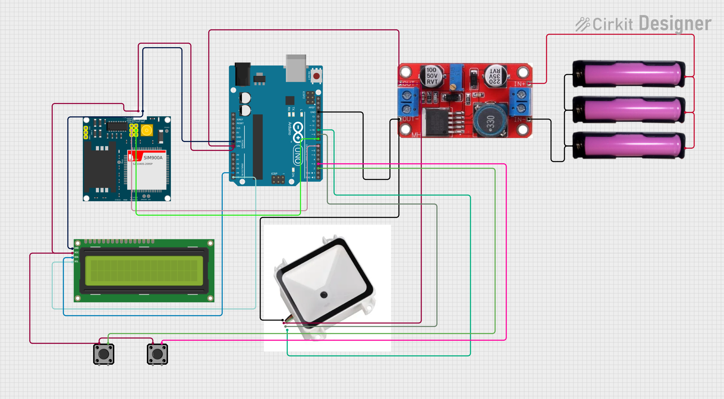
Circuit Documentation
Summary
This circuit integrates various components including an Arduino UNO microcontroller, a SIM900A GSM module, a QR code reader, tactile switch buttons, 18650 battery holders, an XL6015 boost converter, and an I2C LCD 16x2 screen. The Arduino UNO serves as the central processing unit, interfacing with the GSM module for cellular communication, the QR code reader for input, and the LCD screen for output. The tactile switches provide user input, while the 18650 batteries supply power through the boost converter. The circuit is designed for tasks that require user interaction, data scanning, cellular communication, and display feedback.
Component List
Arduino UNO
- Microcontroller board based on the ATmega328P
- Provides digital and analog I/O pins
- Features serial communication capabilities
SIM900A GSM Module
- GSM/GPRS module for cellular communication
- Supports SMS and voice calls
- Requires a power supply and serial communication with a microcontroller
QR Code Reader
- Scans and decodes QR codes
- Communicates with the microcontroller via serial interface
Tactile Switch Buttons - 12mm Square
- Provides a simple user interface
- Normally open pushbutton switches
18650 Battery Holders
- Holds 18650 type rechargeable batteries
- Provides power to the circuit
XL6015 Boost Converter
- Step-up (boost) voltage converter
- Increases the voltage from the batteries to a higher, regulated voltage
I2C LCD 16x2 Screen
- Alphanumeric liquid crystal display
- Uses I2C communication for displaying text
Wiring Details
Arduino UNO
- GND: Connected to the ground of the SIM900A, I2C LCD screen, and QR code reader.
- Vin: Connected to the 5V output of the XL6015 boost converter.
- A4 (SDA): Connected to the SDA pin of the I2C LCD screen.
- A5 (SCL): Connected to the SCL pin of the I2C LCD screen.
- D8: Connected to the 5VR pin of the SIM900A.
- D7: Connected to the 5VT pin of the SIM900A.
- D10: Connected to the TX pin of the QR code reader.
- D9: Connected to the RX pin of the QR code reader.
- D3: Connected to one tactile switch button.
- D2: Connected to another tactile switch button.
SIM900A GSM Module
- GND: Connected to the ground of the Arduino UNO and I2C LCD screen.
- 5V: Connected to the 5V output of the XL6015 boost converter.
QR Code Reader
- GND: Connected to the ground of the Arduino UNO and XL6015 boost converter.
- 5V: Connected to the 5V output of the XL6015 boost converter.
- TX: Connected to the D10 pin of the Arduino UNO.
- RX: Connected to the D9 pin of the Arduino UNO.
Tactile Switch Buttons - 12mm Square
- Pin 1: Connected to the 5V output of the XL6015 boost converter.
- Pin 2: One switch connected to the D3 pin of the Arduino UNO, another to the D2 pin.
18650 Battery Holders
- GND: All holders connected together and to the INPUT - of the XL6015 boost converter.
- VCC: All holders connected together and to the INPUT + of the XL6015 boost converter.
XL6015 Boost Converter
- INPUT -: Connected to the GND of all 18650 battery holders.
- INPUT +: Connected to the VCC of all 18650 battery holders.
- OUTPUT +: Connected to the 5V inputs of the Arduino UNO, SIM900A, QR code reader, and I2C LCD screen.
- OUTPUT -: Connected to the ground of the QR code reader.
I2C LCD 16x2 Screen
- GND: Connected to the ground of the Arduino UNO and SIM900A.
- VCC (5V): Connected to the 5V output of the XL6015 boost converter.
- SDA: Connected to the A4 pin of the Arduino UNO.
- SCL: Connected to the A5 pin of the Arduino UNO.
Documented Code
Arduino UNO Code (sketch.ino)
void setup() {
  // put your setup code here, to run once:

}

void loop() {
  // put your main code here, to run repeatedly:

}
Note: The provided code is a template and does not include specific functionality. It needs to be completed with the logic required for the circuit's intended operation.