
Arduino UNO Based Automated Irrigation System with GSM Control
View and Edit Project In Cirkit Designer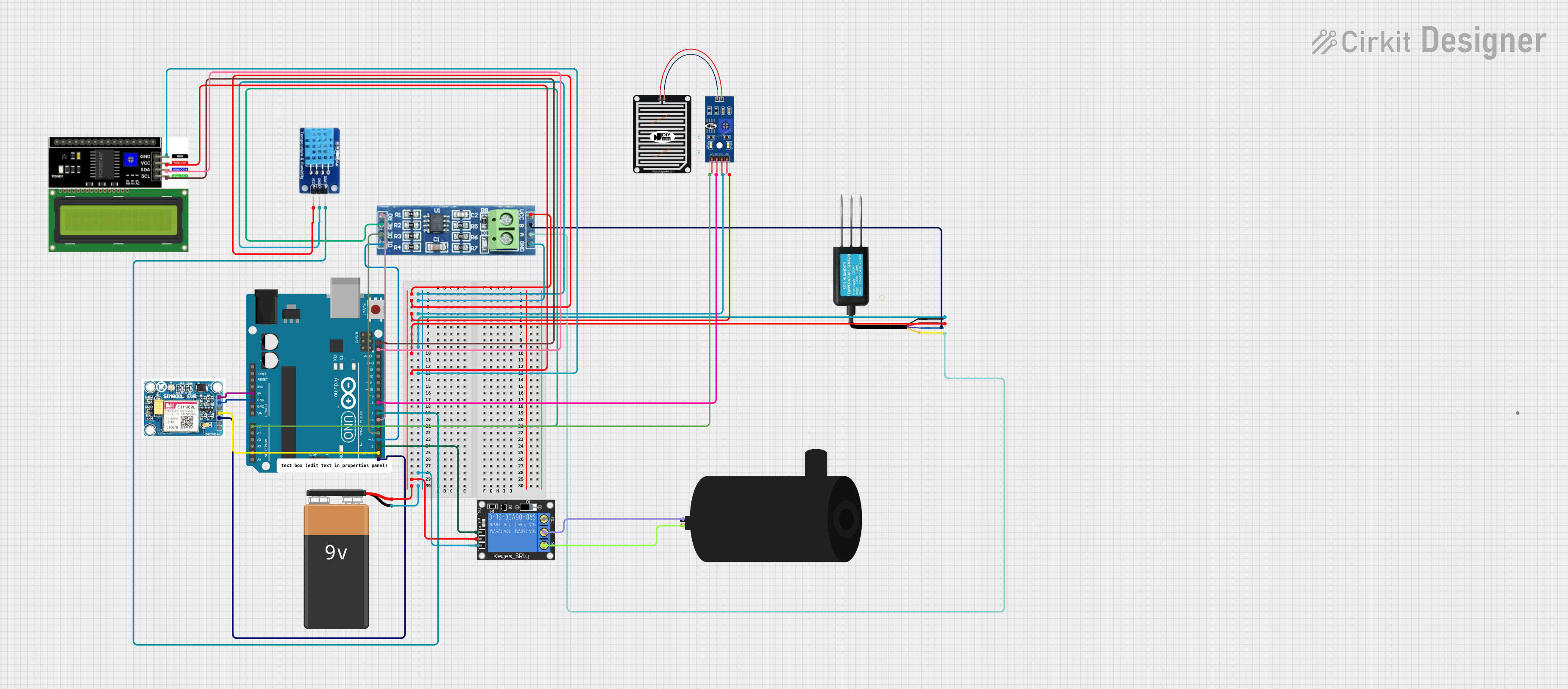
Circuit Documentation
Summary
The circuit is designed to control a 220V fan using various sensors and modules, including a SIM800L GSM module for communication, a DHT11 sensor for temperature and humidity readings, a rain sensor, a soil moisture sensor, and an LCD I2C display for output. The fan is controlled via a 1-Channel Relay, which is operated by the Arduino UNO based on sensor inputs or GSM commands. The system is powered by a 9V battery.
Component List
SIM 800L V2.0 GSM Module
- Description: GSM/GPRS module for communication.
- Pins: SIM_TXD, VDD, SIM.RXD, 5V/4V, GND, RST.
Arduino UNO
- Description: Microcontroller board based on the ATmega328P.
- Pins: UNUSED, IOREF, Reset, 3.3V, 5V, GND, Vin, A0-A5, SCL, SDA, AREF, D0-D13.
1-Channel Relay (5V 10A)
- Description: Relay module for controlling high power devices.
- Pins: NC, signal, C, power, NO, ground.
9V Battery
- Description: Power source for the circuit.
- Pins: -, +.
Soil Moisture Sensor
- Description: Sensor for detecting the moisture level in soil.
- Pins: RS485 - A, VCC, GND, RS485 - B.
RS485 Module
- Description: Module for RS485 communication.
- Pins: VCC, RO, RE, GND, B, A, DE, DI.
DHT11 Sensor
- Description: Sensor for measuring temperature and humidity.
- Pins: DATA, GND, VCC.
Rain Sensor
- Description: Sensor for detecting rain.
- Pins: AO, DO, GRD, VCC.
LCD I2C Display
- Description: Display for showing information.
- Pins: GND, VCC, SDA, SCL.
Water Pump
- Description: Pump for water circulation.
- Pins: positive, negative.
Wiring Details
SIM 800L V2.0 GSM Module
- SIM_TXD connected to Arduino UNO D1.
- SIM.RXD connected to Arduino UNO D0.
- 5V/4V connected to Arduino UNO 5V.
- GND connected to Arduino UNO GND.
Arduino UNO
- 5V and GND used for power distribution to other components.
- A0 connected to Rain Sensor AO.
- D0 and D1 for GSM module communication.
- SCL and SDA connected to LCD I2C Display.
- D2 connected to 1-Channel Relay signal.
- D7 connected to DHT11 DATA.
- D8 connected to Rain Sensor DO.
- D6, D5, D4, and D3 connected to RS485 RO, RE, DE, and DI respectively.
1-Channel Relay (5V 10A)
- power connected to 9V Battery +.
- ground connected to 9V Battery -.
- signal connected to Arduino UNO D2.
- C connected to Water Pump negative.
- NO connected to Water Pump positive.
9V Battery
-
- connected to Relay power and VCC distribution net.
-
- connected to Relay ground and GND distribution net.
Soil Moisture Sensor
- VCC connected to VCC distribution net.
- GND connected to GND distribution net.
- RS485 - A connected to RS485 A.
- RS485 - B connected to RS485 B.
RS485 Module
- VCC connected to VCC distribution net.
- GND connected to GND distribution net.
- RO connected to Arduino UNO D6.
- RE connected to Arduino UNO D5.
- DE connected to Arduino UNO D4.
- DI connected to Arduino UNO D3.
- A connected to Soil Moisture Sensor RS485 - A.
- B connected to Soil Moisture Sensor RS485 - B.
DHT11 Sensor
- DATA connected to Arduino UNO D7.
- VCC connected to VCC distribution net.
- GND connected to GND distribution net.
Rain Sensor
- AO connected to Arduino UNO A0.
- DO connected to Arduino UNO D8.
- VCC connected to VCC distribution net.
- GRD connected to GND distribution net.
LCD I2C Display
- SDA connected to Arduino UNO SDA.
- SCL connected to Arduino UNO SCL.
- VCC connected to VCC distribution net.
- GND connected to GND distribution net.
Water Pump
- positive connected to Relay NO.
- negative connected to Relay C.
Documented Code
/*
 * Arduino Sketch to control a 220V fan using a 1-Channel Relay, SIM800L GSM module,
 * DHT11 sensor, Rain Sensor, Soil Moisture Sensor, and LCD I2C Display.
 * The fan is controlled via a relay connected to pin D2 of the Arduino.
 * The SIM800L module is used for GSM communication and is connected to pins D0 and D1.
 * The fan will be turned on or off based on commands received via GSM or sensor readings.
 * The LCD displays temperature, humidity, and fan status.
 */

#include <SoftwareSerial.h>
#include <Wire.h>
#include <LiquidCrystal_I2C.h>
#include <DHT.h>

// Pin definitions
const int relayPin = 2; // Relay control pin
const int simTxPin = 1; // SIM800L TX pin
const int simRxPin = 0; // SIM800L RX pin
const int dhtPin = 7; // DHT11 data pin
const int rainAnalogPin = A0; // Rain sensor analog pin
const int rainDigitalPin = 8; // Rain sensor digital pin
const int soilMoisturePin = 3; // Soil moisture sensor pin

// Create a SoftwareSerial object for SIM800L communication
SoftwareSerial sim800l(simRxPin, simTxPin);

// Create a DHT object
DHT dht(dhtPin, DHT11);

// Create an LCD object
LiquidCrystal_I2C lcd(0x27, 16, 2);

void setup() {
  // Initialize relay pin as output
  pinMode(relayPin, OUTPUT);
  digitalWrite(relayPin, LOW); // Ensure fan is off initially

  // Initialize serial communication for debugging
  Serial.begin(9600);

  // Initialize SIM800L communication
  sim800l.begin(9600);
  Serial.println("SIM800L initialized.");

  // Initialize DHT11 sensor
  dht.begin();

  // Initialize LCD
  lcd.init();
  lcd.backlight();
  lcd.setCursor(0, 0);
  lcd.print("Initializing...");
}

void loop() {
  // Read temperature and humidity from DHT11
  float temperature = dht.readTemperature();
  float humidity = dht.readHumidity();

  // Read rain sensor values
  int rainAnalogValue = analogRead(rainAnalogPin);
  int rainDigitalValue = digitalRead(rainDigitalPin);

  // Read soil moisture sensor value
  int soilMoistureValue = analogRead(soilMoisturePin);

  // Check for incoming messages from SIM800L
  if (sim800l.available()) {
    String message = sim800l.readString();
    Serial.println("Message received: " + message);

    // Check for fan control commands
    if (message.indexOf("FAN ON") >= 0) {
      digitalWrite(relayPin, HIGH); // Turn fan on
      Serial.println("Fan turned ON.");
    } else if (message.indexOf("FAN OFF") >= 0) {
      digitalWrite(relayPin, LOW); // Turn fan off
      Serial.println("Fan turned OFF.");
    }
  }

  // Control fan based on sensor readings
  if (rainDigitalValue == LOW || soilMoistureValue > 500) {
    digitalWrite(relayPin, LOW); // Turn fan off
  }

  // Update LCD display
  lcd.clear();
  lcd.setCursor(0, 0);
  lcd.print("Temp: ");
  lcd.print(temperature);
  lcd.print("C");
  lcd.setCursor(0, 1);
  lcd.print("Humidity: ");
  lcd.print(humidity);
  lcd.print("%");
  lcd.setCursor(0, 2);
  lcd.print("Fan: ");
  lcd.print(digitalRead(relayPin) == HIGH ? "ON" : "OFF");

  // Add a small delay to avoid overwhelming the serial buffer
  delay(1000);
}
This code is responsible for reading sensor data, controlling the relay based on sensor inputs or GSM commands, and updating the LCD display with the current temperature, humidity, and fan status. The SoftwareSerial library is used for communication with the SIM800L GSM module, and the LiquidCrystal_I2C library is used for the LCD display. The DHT library is used to interface with the DHT11 sensor.