Cirkit Designer
Your all-in-one circuit design IDE
Home /
Project Documentation
9V Battery-Powered DC Motor Control with LED Indicator and Voltage Regulation
Circuit Documentation
Summary of the Circuit
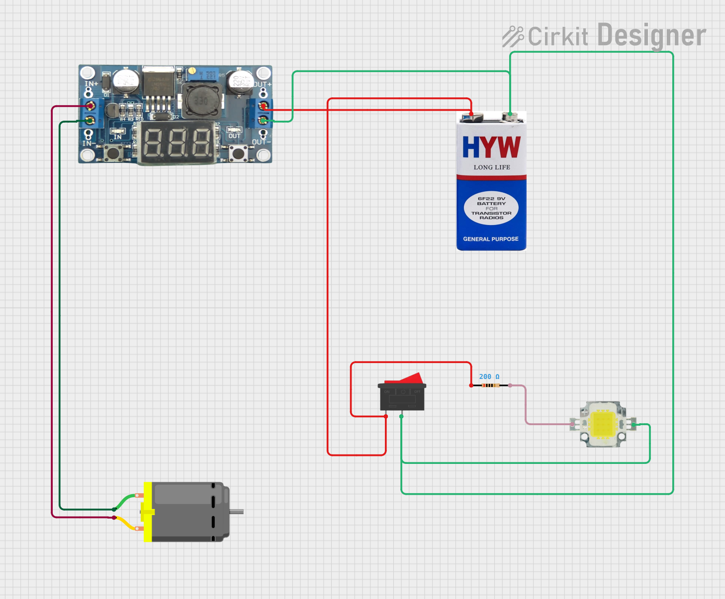
This circuit appears to be a simple power regulation and distribution system designed to drive a DC motor and a power LED from a 9V battery source. The circuit includes a DC-DC converter to regulate the voltage, a rocker switch to control the power flow, a resistor to limit the current to the LED, and the load components (the DC motor and the power LED).
Component List
DC Motor
- Description: A standard DC motor that converts electrical energy into mechanical rotation.
- Pins: 2 pins for power connection.
LM296 DC-DC Converter
- Description: A voltage regulator that steps down the input voltage to a lower output voltage.
- Pins: Vin (input voltage), GNDin (input ground), Vout (output voltage), GNDout (output ground).
Rocker Switch
- Description: A mechanical switch that allows for breaking or connecting the circuit by rocking the switch to one side or the other.
- Pins: 2 pins for opening or closing the electrical circuit.
Power LED 12V 10W 0.8-0.9A
- Description: A high-power LED that operates at 12V and consumes between 0.8 to 0.9A.
- Pins: + (positive), - (negative).
Resistor
- Description: A passive two-terminal electrical component that provides resistance to the flow of current.
- Properties: 200 Ohms resistance.
- Pins: 2 pins for connecting to the circuit.
9V Battery
- Description: A standard 9V battery that provides the power source for the circuit.
- Pins: + (positive), - (negative).
Wiring Details
DC Motor
- Pin 1: Connected to GNDin of the LM296 DC-DC Converter.
- Pin 2: Connected to Vin of the LM296 DC-DC Converter.
LM296 DC-DC Converter
- Vin: Connected to pin 2 of the DC Motor.
- GNDin: Connected to pin 1 of the DC Motor.
- Vout: Connected to the + pin of the 9V battery, pin 1 of the Rocker Switch, and pin1 of the Resistor.
- GNDout: Connected to the - pin of the 9V battery, the - pin of the Power LED, and pin 2 of the Rocker Switch.
Rocker Switch
- Pin 1: Connected to Vout of the LM296 DC-DC Converter.
- Pin 2: Connected to GNDout of the LM296 DC-DC Converter.
Power LED 12V 10W 0.8-0.9A
- +: Connected to pin2 of the Resistor.
- -: Connected to GNDout of the LM296 DC-DC Converter.
Resistor
- Pin1: Connected to Vout of the LM296 DC-DC Converter.
- Pin2: Connected to the + pin of the Power LED.
9V Battery
- +: Connected to Vout of the LM296 DC-DC Converter.
- -: Connected to GNDout of the LM296 DC-DC Converter.
Documented Code
There is no embedded code provided for any microcontrollers in this circuit. Therefore, this section is not applicable to the current documentation.