
NPN Transistor-Based Signal Amplifier with Frequency Filtering
View and Edit Project In Cirkit Designer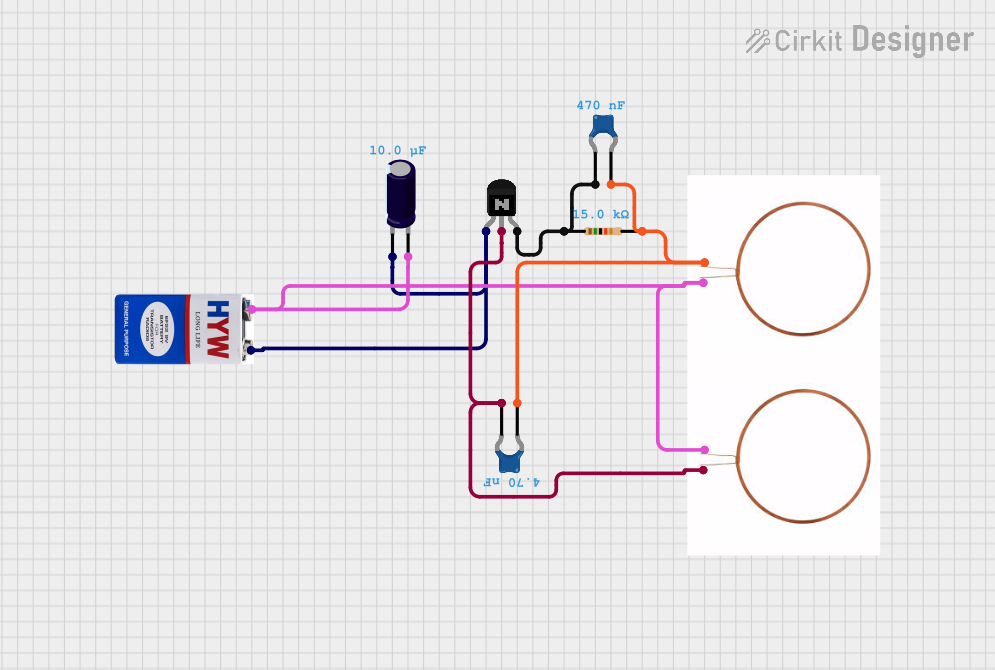
Circuit Documentation
Summary of the Circuit
This circuit appears to be a simple analog circuit that includes a combination of passive components (capacitors, resistor, and coils) and an active component (NPN transistor). The circuit is powered by a 9V battery. The capacitors may be used for filtering or timing purposes, the resistor sets a current or voltage level, and the coils could be part of an inductive element or a transformer setup. The NPN transistor is likely used as a switch or amplifier. Without a specific schematic or further context, the exact functionality of the circuit cannot be determined.
Component List
NPN Transistor (EBC)
- Description: A bipolar junction transistor with emitter, base, and collector pins.
- Purpose: Typically used for amplification or switching.
9V Battery
- Description: A standard 9-volt battery with positive and negative terminals.
- Purpose: Provides power to the circuit.
Electrolytic Capacitor
- Description: A polarized capacitor with a capacitance of 10 µF (0.00001 Farads).
- Purpose: Commonly used for power supply filtering or energy storage.
Copper Coil
- Description: An inductive component with two terminals.
- Purpose: Could be used for creating magnetic fields, inductance, or as part of a transformer.
Resistor
- Description: A passive component with a resistance of 15 kΩ (15000 Ohms).
- Purpose: Used to limit current or divide voltages in the circuit.
Ceramic Capacitor
- Description: Non-polarized capacitors with capacitances of 470 nF (4.7e-7 Farads) and 4.7 nF (4.7e-9 Farads).
- Purpose: Often used for decoupling, filtering, or timing applications.
Wiring Details
NPN Transistor (EBC)
- Emitter connected to:
- Negative terminal of the Electrolytic Capacitor
- Negative terminal of the 9V Battery
- Base connected to:
- Pin 1 of the smaller Ceramic Capacitor (4.7 nF)
- Positive terminal of one Copper Coil
- Collector connected to:
- Pin 1 of the Resistor
- Pin 0 of the larger Ceramic Capacitor (470 nF)
9V Battery
- Positive (+) terminal connected to:
- Positive terminal of the Electrolytic Capacitor
- Positive terminal of one Copper Coil
- Negative (-) terminal connected to:
- Emitter of the NPN Transistor
- Negative terminal of the Electrolytic Capacitor
Electrolytic Capacitor
- Positive (+) terminal connected to:
- Positive terminal of the 9V Battery
- Positive terminal of one Copper Coil
- Negative (-) terminal connected to:
- Emitter of the NPN Transistor
- Negative terminal of the 9V Battery
Copper Coil
- Positive (+ve) terminal of the first coil connected to:
- Base of the NPN Transistor
- Positive terminal of the Electrolytic Capacitor
- Negative (-ve) terminal of the first coil connected to:
- Pin 0 of the larger Ceramic Capacitor (470 nF)
- Pin 0 of the smaller Ceramic Capacitor (4.7 nF)
- Pin 2 of the Resistor
Resistor
- Pin 1 connected to:
- Collector of the NPN Transistor
- Pin 2 connected to:
- Pin 0 of the smaller Ceramic Capacitor (4.7 nF)
- Pin 1 of the larger Ceramic Capacitor (470 nF)
- Negative terminal of one Copper Coil
Ceramic Capacitor (470 nF)
- Pin 0 connected to:
- Collector of the NPN Transistor
- Pin 1 connected to:
- Pin 2 of the Resistor
Ceramic Capacitor (4.7 nF)
- Pin 0 connected to:
- Pin 2 of the Resistor
- Pin 1 connected to:
- Base of the NPN Transistor
Documented Code
There is no embedded code provided for this circuit as there are no microcontroller components listed. If a microcontroller is added to the circuit in the future, the code section will be updated accordingly to include the necessary embedded code and its documentation.