
Arduino Mega 2560 Controlled Interactive Display with RTC, Keypad, and Flame Sensor
View and Edit Project In Cirkit Designer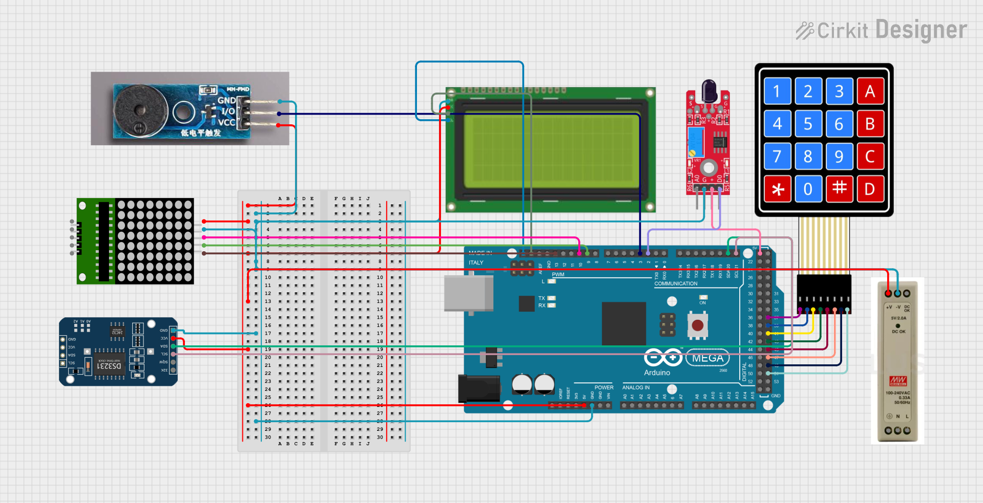
Circuit Documentation
Summary
This circuit integrates various components including a 4x4 membrane matrix keypad, an LCD with I2C interface, two 5V power supply units (PSUs), an Arduino Mega 2560 microcontroller, a DS3231 real-time clock (RTC), a passive buzzer module, an 8x8 LED matrix, and a KY-026 flame sensor. The Arduino Mega 2560 serves as the central processing unit, interfacing with the input devices (keypad, flame sensor), output devices (LCD, buzzer, LED matrix), and the RTC for timekeeping. The circuit is powered by the 5V PSUs, which provide the necessary voltage to the components.
Component List
4X4 Membrane Matrix Keypad
- A 4x4 matrix keypad used for user input.
Lcd 20x4 i2c
- A 20x4 character LCD display with an I2C interface for displaying information.
5V PSU
- Two 5V power supply units that provide power to the circuit.
Arduino Mega 2560
- A microcontroller board based on the ATmega2560, with numerous digital and analog I/O pins.
DS3231 RTC
- A real-time clock module for maintaining accurate time.
Passive Buzzer Module
- A module that can produce simple tones when provided with a signal.
8*8 matrix
- An 8x8 LED matrix display for visual output.
KY-026 Flame Sensor
- A sensor module for detecting flames or fire.
Wiring Details
4X4 Membrane Matrix Keypad
- Rows R1 to R4 are connected to pins D37 to D43 on the Arduino Mega 2560.
- Columns C1 to C4 are connected to pins D45 to D51 on the Arduino Mega 2560.
Lcd 20x4 i2c
- GND to GND on the PSU.
- 5v to 5V+ on the PSU.
- SCA to SDA on the Arduino Mega 2560.
- SCL to SCL on the Arduino Mega 2560.
5V PSU
- 5V+ and GND are used to power various components in the circuit.
Arduino Mega 2560
- 5V and GND pins are used to power the board and connected components.
- SDA and SCL are used for I2C communication with the LCD and RTC.
- Digital pins D2, D3, D9, D10, and D13 are used to interface with the flame sensor, buzzer, and 8x8 LED matrix.
DS3231 RTC
- SCL to D21/SCL on the Arduino Mega 2560.
- SDA to D20/SDA on the Arduino Mega 2560.
- VCC to 5V+ on the PSU.
- GND to GND on the PSU.
Passive Buzzer Module
- I/O to D3 PWM on the Arduino Mega 2560.
- VCC to 5V+ on the PSU.
- GND to GND on the PSU.
8*8 matrix
- DIN to D10 PWM on the Arduino Mega 2560.
- CLK to D9 PWM on the Arduino Mega 2560.
- CS to D13 PWM on the Arduino Mega 2560.
- VCC to 5V+ on the PSU.
- GND to GND on the PSU.
KY-026 Flame Sensor
- DO to D2 PWM on the Arduino Mega 2560.
- VCC to 5V on the Arduino Mega 2560.
- GND to GND on the PSU.
Documented Code
Arduino Mega 2560 - sketch.ino
void setup() {
  // put your setup code here, to run once:

}

void loop() {
  // put your main code here, to run repeatedly:

}
Arduino Mega 2560 - documentation.txt
(No additional documentation provided for the code)
This concludes the documentation for the provided circuit. The circuit is designed to perform various tasks based on the components used and their interconnections. The Arduino Mega 2560, being the central controller, is programmed to interact with all the peripherals to achieve the desired functionality.