
Arduino Mega 2560 Controlled Ultrasonic Sensing and GSM Communication System
View and Edit Project In Cirkit Designer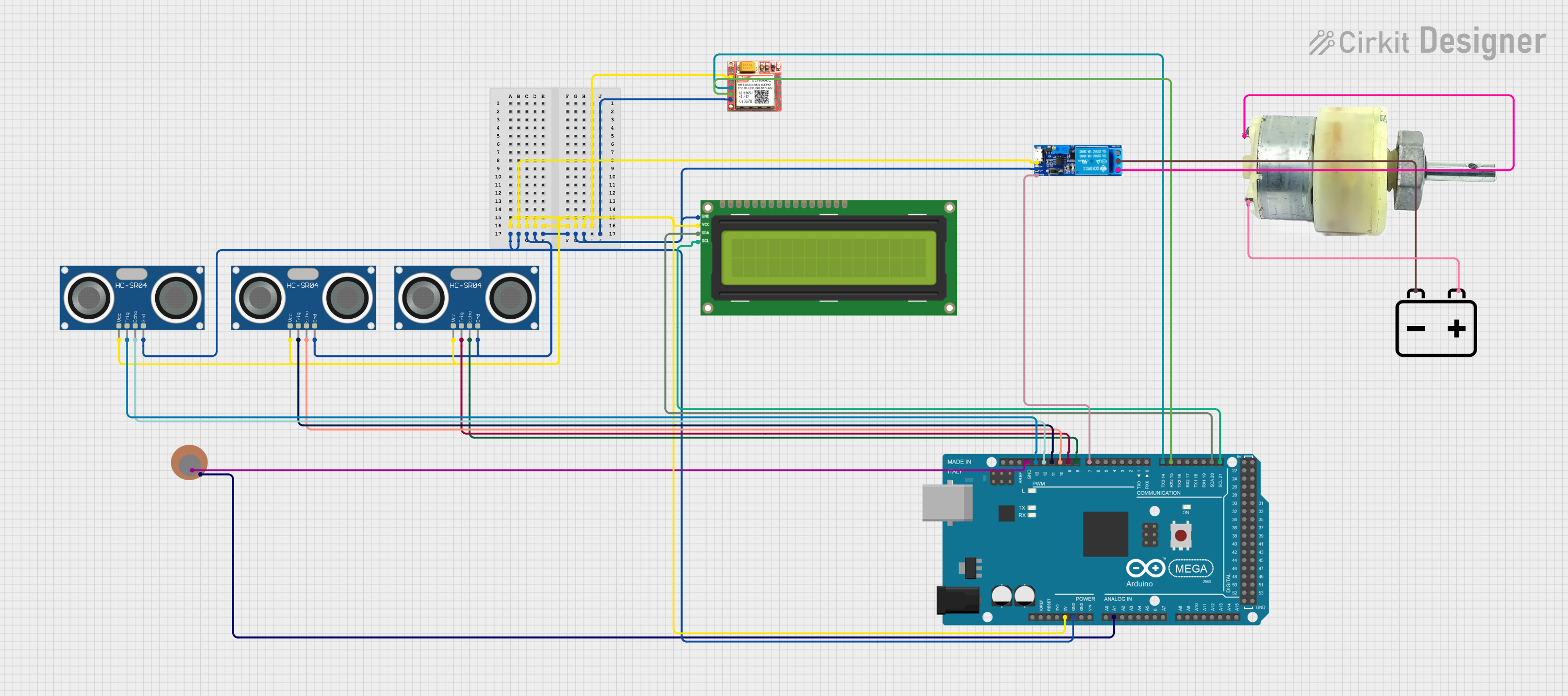
Circuit Documentation
Summary
This circuit integrates various components controlled by an Arduino Mega 2560 microcontroller to perform a range of functions. The circuit includes ultrasonic sensors (HC-SR04) for distance measurement, an I2C LCD screen for data display, a piezo sensor for detecting vibrations, a relay module for controlling power to a 12V geared motor, a SIM800L module for cellular communication, and a 12V battery as the power source.
Component List
Arduino Mega 2560
- Microcontroller board based on the ATmega2560
- It has 54 digital input/output pins, 16 analog inputs, 4 UARTs, a 16 MHz crystal oscillator, a USB connection, a power jack, an ICSP header, and a reset button.
HC-SR04 Ultrasonic Sensor (x3)
- Ultrasonic distance measuring module
- Uses sonar to determine the distance to an object
- Features VCC, TRIG, ECHO, and GND pins
I2C LCD 16x2 Screen
- Alphanumeric liquid crystal display
- 16 characters wide, 2 rows
- Communicates over I2C protocol
Piezo Sensor
- Sensor that can detect vibration, touch, or shock
- Has a positive and a negative terminal
Relay Module 5V-30V
- Electrically operated switch
- Can be used to control higher power circuits with a low power signal
- Has common contact, normally open, normally closed, trigger, V-, and V+ pins
12V Geared Motor
- Electric motor with a gearbox for torque multiplication
- Has two terminals for electrical connection
SIM800L
- GSM/GPRS module
- Can be used for mobile communication such as sending SMS, making calls, etc.
- Features multiple pins including VCC, GND, RXD, TXD, etc.
12V Battery
- Power source for the motor and relay module
- Has a positive and a negative terminal
Wiring Details
Arduino Mega 2560
- 5V connected to VCC of I2C LCD, HC-SR04 sensors, Relay module, and SIM800L
- GND connected to GND of I2C LCD, HC-SR04 sensors, Relay module, SIM800L, and Piezo Sensor
- A1 connected to Piezo Sensor (-)
- D21/SCL connected to I2C LCD SCL
- D20/SDA connected to I2C LCD SDA
- D15/RX3 connected to SIM800L TXD
- D14/TX3 connected to SIM800L RXD
- D7 PWM connected to Relay module trigger
- D8 PWM connected to HC-SR04 ECHO (Sensor 2)
- D9 PWM connected to HC-SR04 TRIG (Sensor 2)
- D10 PWM connected to HC-SR04 ECHO (Sensor 3)
- D11 PWM connected to HC-SR04 TRIG (Sensor 3)
- D12 PWM connected to HC-SR04 ECHO (Sensor 1)
- D13 PWM connected to HC-SR04 TRIG (Sensor 1)
HC-SR04 Ultrasonic Sensor (Sensor 1)
- VCC connected to 5V from Arduino
- GND connected to GND from Arduino
- ECHO connected to D12 PWM on Arduino
- TRIG connected to D13 PWM on Arduino
HC-SR04 Ultrasonic Sensor (Sensor 2)
- VCC connected to 5V from Arduino
- GND connected to GND from Arduino
- ECHO connected to D8 PWM on Arduino
- TRIG connected to D9 PWM on Arduino
HC-SR04 Ultrasonic Sensor (Sensor 3)
- VCC connected to 5V from Arduino
- GND connected to GND from Arduino
- ECHO connected to D10 PWM on Arduino
- TRIG connected to D11 PWM on Arduino
I2C LCD 16x2 Screen
- VCC (5V) connected to 5V from Arduino
- GND connected to GND from Arduino
- SCL connected to D21/SCL on Arduino
- SDA connected to D20/SDA on Arduino
Piezo Sensor
- (+) connected to GND on Arduino (for simplicity in this example, though typically would connect to an I/O pin)
- (-) connected to A1 on Arduino
Relay Module 5V-30V
- V+ connected to 5V from Arduino
- V- connected to GND from Arduino
- Trigger connected to D7 PWM on Arduino
- Common contact connected to negative terminal of 12V Battery
- Normally open connected to Terminal 1 of 12V Geared Motor
12V Geared Motor
- Terminal 1 connected to normally open on Relay module
- Terminal 2 connected to positive terminal of 12V Battery
SIM800L
- VCC connected to 5V from Arduino
- GND connected to GND from Arduino
- TXD connected to D15/RX3 on Arduino
- RXD connected to D14/TX3 on Arduino
12V Battery
- (+) connected to Terminal 2 of 12V Geared Motor
- (-) connected to common contact of Relay module
Documented Code
Arduino Mega 2560 - sketch.ino
void setup() {
  // put your setup code here, to run once:

}

void loop() {
  // put your main code here, to run repeatedly:

}
Arduino Mega 2560 - documentation.txt
(No additional documentation provided for the code)