
Arduino UNO-Based Smart Weather Station with GSM and I2C LCD Display
View and Edit Project In Cirkit Designer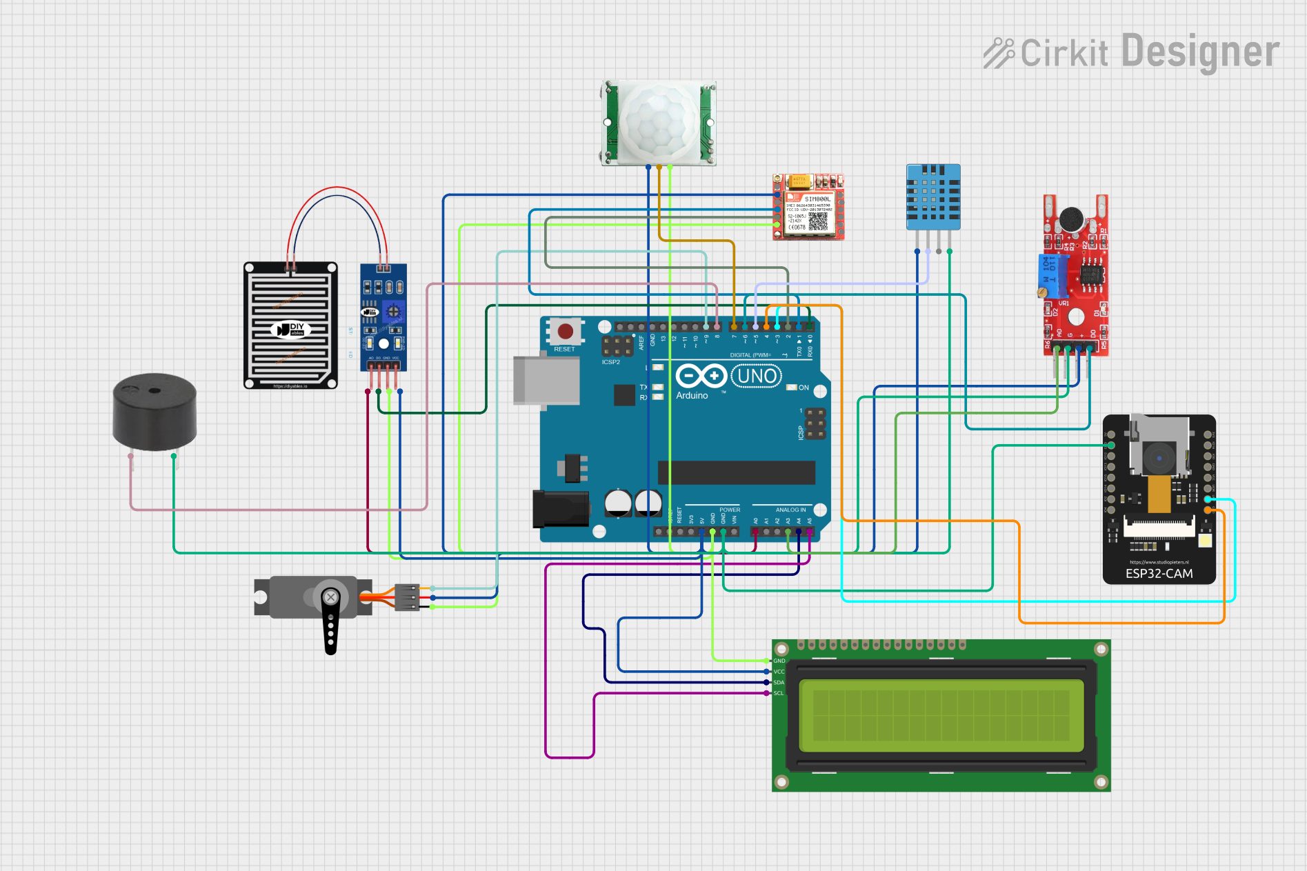
Circuit Documentation
Summary
This document provides a detailed overview of a circuit that integrates various sensors, an LCD display, a servo motor, a GSM module, and an ESP32-CAM module, all controlled by an Arduino UNO. The circuit is designed to monitor environmental conditions such as temperature, humidity, motion, sound, and rain, and to display the data on an LCD screen. Additionally, it can send SMS alerts using the GSM module and control a servo motor.
Component List
Arduino UNO
- Description: Microcontroller board based on the ATmega328P.
- Pins: UNUSED, IOREF, Reset, 3.3V, 5V, GND, Vin, A0, A1, A2, A3, A4, A5, SCL, SDA, AREF, D13, D12, D11, D10, D9, D8, D7, D6, D5, D4, D3, D2, D1, D0
16x2 I2C LCD
- Description: 16x2 character LCD display with I2C interface.
- Pins: GND, VCC, SDA, SCL
RAIN SENSOR
- Description: Sensor to detect rain.
- Pins: AO, DO, GRD, VCC
SIM 800L
- Description: GSM module for sending SMS.
- Pins: NFT, RING, VCC, DTR, RST, MIC +, RXD, MIC-, TXD, SPK+, GND, SPK-
DHT11 Humidity and Temperature Sensor
- Description: Sensor to measure temperature and humidity.
- Pins: VDD, DATA, NULL, GND
Servo
- Description: Servo motor for mechanical movement.
- Pins: GND, VCC, PWM
Buzzer
- Description: Simple buzzer for sound output.
- Pins: PIN, GND
KY 038
- Description: Sound sensor module.
- Pins: +, G, A0, D0
PIR/Motion Sensor
- Description: Sensor to detect motion.
- Pins: GND, OUTPUT, VCC
ESP32-CAM
- Description: Camera module with ESP32.
- Pins: 5V, GND, IO12, IO13, IO15, IO14, IO2, IO4, VOT, VOR, VCC, IO0, IO16, 3V3
Wiring Details
Arduino UNO
- 5V: Connected to VCC of 16x2 I2C LCD, RAIN SENSOR, PIR/Motion Sensor, SIM 800L, KY 038, DHT11 Humidity and Temperature Sensor, and Servo.
- GND: Connected to GND of 16x2 I2C LCD, RAIN SENSOR, PIR/Motion Sensor, SIM 800L, KY 038, DHT11 Humidity and Temperature Sensor, Servo, Buzzer, and ESP32-CAM.
- A0: Connected to AO of RAIN SENSOR.
- A3: Connected to A0 of KY 038.
- A4: Connected to SDA of 16x2 I2C LCD.
- A5: Connected to SCL of 16x2 I2C LCD.
- D9: Connected to PWM of Servo.
- D8: Connected to PIN of Buzzer.
- D7: Connected to OUTPUT of PIR/Motion Sensor.
- D6: Connected to D0 of KY 038.
- D5: Connected to DATA of DHT11 Humidity and Temperature Sensor.
- D4: Connected to GND of ESP32-CAM.
- D3: Connected to VOT of ESP32-CAM.
- D2: Connected to TXD of SIM 800L.
- D1: Connected to RXD of SIM 800L.
- D0: Connected to DO of RAIN SENSOR.
16x2 I2C LCD
- VCC: Connected to 5V of Arduino UNO.
- GND: Connected to GND of Arduino UNO.
- SDA: Connected to A4 of Arduino UNO.
- SCL: Connected to A5 of Arduino UNO.
RAIN SENSOR
- VCC: Connected to 5V of Arduino UNO.
- GRD: Connected to GND of Arduino UNO.
- AO: Connected to A0 of Arduino UNO.
- DO: Connected to D0 of Arduino UNO.
SIM 800L
- VCC: Connected to 5V of Arduino UNO.
- GND: Connected to GND of Arduino UNO.
- TXD: Connected to D2 of Arduino UNO.
- RXD: Connected to D1 of Arduino UNO.
DHT11 Humidity and Temperature Sensor
- VDD: Connected to 5V of Arduino UNO.
- DATA: Connected to D5 of Arduino UNO.
- GND: Connected to GND of Arduino UNO.
Servo
- VCC: Connected to 5V of Arduino UNO.
- GND: Connected to GND of Arduino UNO.
- PWM: Connected to D9 of Arduino UNO.
Buzzer
- PIN: Connected to D8 of Arduino UNO.
- GND: Connected to GND of Arduino UNO.
KY 038
- +: Connected to 5V of Arduino UNO.
- G: Connected to GND of Arduino UNO.
- A0: Connected to A3 of Arduino UNO.
- D0: Connected to D6 of Arduino UNO.
PIR/Motion Sensor
- VCC: Connected to 5V of Arduino UNO.
- GND: Connected to GND of Arduino UNO.
- OUTPUT: Connected to D7 of Arduino UNO.
ESP32-CAM
- GND: Connected to GND of Arduino UNO.
- VOT: Connected to D3 of Arduino UNO.
Documented Code
#include <DHT.h>
#include <LiquidCrystal_I2C.h>
#include <Servo.h>
#include <SoftwareSerial.h>

// Pin Definitions
#define PIR_PIN 7
#define SOUND_SENSOR_PIN 6
#define RAIN_SENSOR_PIN A0
#define DHT_PIN 5
#define GSM_RX 10
#define GSM_TX 11
#define LCD_ADDRESS 0x27
#define SERVO_PIN 9

// Setup for DHT11 sensor
DHT dht(DHT_PIN, DHT11);

// Setup for LCD display
LiquidCrystal_I2C lcd(LCD_ADDRESS, 16, 2);

// Setup for Servo motor
Servo myServo;

// Setup for GSM module
SoftwareSerial gsmSerial(GSM_RX, GSM_TX);

// Setup for other components
int pirState = 0;
int soundThreshold = 500;  // Threshold for sound sensor
int rainThreshold = 500;   // Adjust depending on your rain sensor readings

void setup() {
  // Initialize Serial Monitor
  Serial.begin(9600);

  // Setup DHT sensor
  dht.begin();

  // Setup LCD
  lcd.begin(16, 2);
  lcd.print("System Initializing...");

  // Setup PIR Sensor
  pinMode(PIR_PIN, INPUT);

  // Setup sound sensor
  pinMode(SOUND_SENSOR_PIN, INPUT);

  // Setup GSM Module
  gsmSerial.begin(9600);

  // Setup Servo motor
  myServo.attach(SERVO_PIN);

  // Setup Rain Sensor
  pinMode(RAIN_SENSOR_PIN, INPUT);

  delay(2000);  // Wait for sensor setup
}

void loop() {
  // Read PIR sensor
  pirState = digitalRead(PIR_PIN);
  if (pirState == HIGH) {
    lcd.clear();
    lcd.print("Motion Detected!");
    delay(1000);
  }

  // Read Sound Sensor (KY-038)
  int soundValue = analogRead(SOUND_SENSOR_PIN);
  if (soundValue > soundThreshold) {
    lcd.clear();
    lcd.print("Sound Detected!");
    delay(1000);
  }

  // Read Rain Sensor
  int rainValue = analogRead(RAIN_SENSOR_PIN);
  if (rainValue > rainThreshold) {
    lcd.clear();
    lcd.print("Rain Detected!");
    sendSMS("Rain Detected!");
    delay(1000);
  }

  // Read DHT11 sensor for temperature and humidity
  float temperature = dht.readTemperature();
  float humidity = dht.readHumidity();

  if (isnan(temperature) || isnan(humidity)) {
    lcd.clear();
    lcd.print("Failed to read DHT!");
  } else {
    lcd.clear();
    lcd.print("Temp: ");
    lcd.print(temperature);
    lcd.print("C");
    lcd.setCursor(0, 1);
    lcd.print("Humidity: ");
    lcd.print(humidity);
    lcd.print("%");
    delay(2000);
  }

  // Control Servo motor (e.g., swing the cradle)