Cirkit Designer
Your all-in-one circuit design IDE
Home /
Project Documentation
Digital Logic State Indicator with Flip-Flops and Logic Gates

Circuit Documentation
Summary
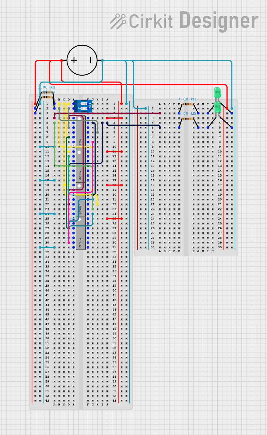
This document provides a detailed overview of a digital logic circuit. The circuit comprises various logic gates, flip-flops, a DC power source, resistors, LEDs, and a DIP switch. The circuit's functionality is determined by the interconnection of these components, which are used to create specific logic functions and signal pathways. The circuit does not include any microcontroller code as none was provided.
Component List
DC Power Source
- Description: Provides the voltage necessary for powering the circuit.
- Pins: Ground, Positive
4013 Dual D-Type Flip-Flop
- Description: A dual D-type flip-flop with set and reset capabilities.
- Pins: Q1, Q1Bar, Clk1, C1, D1, S1, GND, VCC, Q2, Q2Bar, Clk2, C2, D2, S2
74HC32 Quad 2-Input OR Gate
- Description: A quad 2-input OR gate used for logic operations.
- Pins: A1, B1, Y1, A2, B2, Y2, GND, VCC, B4, A4, Y4, B3, A3, Y3
74HC08 Quad 2-Input AND Gate
- Description: A quad 2-input AND gate used for logic operations.
- Pins: A1, B1, Y1, A2, B2, Y2, GND, VCC, B4, A4, Y4, B3, A3, Y3
74HC04 Hex Inverter
- Description: A hex inverter used to invert signal levels.
- Pins: A1, Y1, A2, Y2, A3, Y3, GND, VCC, A6, Y6, A5, Y5, A4, Y4
DIP Switch (2 Position)
- Description: A dual-position DIP switch used for user input.
- Pins: 1, 2, 3, 4
Resistor (1 kOhm)
- Description: A resistor with a resistance of 1 kOhm.
- Pins: pin1, pin2
LED: Two Pin (green)
- Description: A green LED used for indicating output states.
- Pins: cathode, anode
Wiring Details
DC Power Source
- Positive connected to VCC of all ICs and one side of all resistors.
- Ground connected to GND of all ICs, anode of LEDs.
4013 Dual D-Type Flip-Flop
- Q1 connected to 74HC08 (A1).
- Q1Bar connected to 74HC08 (A3).
- Clk1 connected to DIP Switch (2) through a 1 kOhm resistor.
- Clk2 connected to DIP Switch (2) through a 1 kOhm resistor.
- D1 connected to 74HC32 (Y1).
- D2 connected to 74HC32 (Y2).
- VCC connected to DC Power Source (Positive).
- GND connected to DC Power Source (Ground).
74HC32 Quad 2-Input OR Gate
- A1 connected to 74HC08 (Y1).
- B1 connected to 74HC08 (Y4).
- Y1 connected to 4013 (D1).
- A2 connected to 74HC08 (Y2).
- B2 connected to 74HC08 (Y3).
- Y2 connected to 4013 (D2).
- VCC connected to DC Power Source (Positive).
- GND connected to DC Power Source (Ground).
74HC08 Quad 2-Input AND Gate
- A1 connected to 74HC04 (A1) and DIP Switch (1) through a 1 kOhm resistor.
- B1 connected to 4013 (Q1) through a 1 kOhm resistor.
- Y1 connected to 74HC32 (A1).
- A2 connected to 74HC04 (Y1).
- B2 connected to 4013 (Q2) through a 1 kOhm resistor.
- Y2 connected to 74HC32 (A2).
- A3 connected to 4013 (Q1Bar).
- B3 connected to DIP Switch (1) through a 1 kOhm resistor.
- A4 connected to 4013 (Q2).
- B4 connected to DIP Switch (1) through a 1 kOhm resistor.
- Y3 connected to 74HC32 (B2).
- Y4 connected to 74HC32 (B1).
- VCC connected to DC Power Source (Positive).
- GND connected to DC Power Source (Ground).
74HC04 Hex Inverter
- A1 connected to DIP Switch (1) through a 1 kOhm resistor.
- Y1 connected to 74HC08 (A2).
- VCC connected to DC Power Source (Positive).
- GND connected to DC Power Source (Ground).
DIP Switch (2 Position)
- 1 connected to 74HC04 (A1), 74HC08 (A1, B3, B4) through 1 kOhm resistors.
- 2 connected to 4013 (Clk1, Clk2) through 1 kOhm resistors.
Resistor (1 kOhm)
- Four resistors are used, each connected between the DIP Switch and various other components as detailed above.
LED: Two Pin (green)
- Cathode of each LED connected to GND of DC Power Source through a 1 kOhm resistor.
- Anode of each LED connected to GND of DC Power Source.
Documented Code
No code was provided for any microcontrollers in the circuit. Therefore, this section is not applicable to the current documentation.