
Arduino UNO and ILI9341 Display Interface for Custom Graphics
View and Edit Project In Cirkit Designer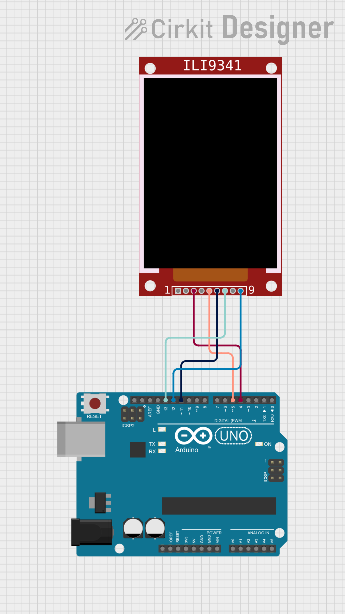
Circuit Documentation
Summary
This circuit involves an Arduino UNO microcontroller interfacing with an ILI9341 display module. The Arduino UNO is used to control the display, sending commands and data to render graphics on the screen. The communication between the Arduino and the ILI9341 display is achieved through SPI (Serial Peripheral Interface).
Component List
ILI9341 Display Module
- Description: A 240x320 pixel TFT LCD display with SPI interface.
- Pins: VCC, GND, CS, RST, D/C, MOSI, SCK, LED, MISO
Arduino UNO
- Description: A microcontroller board based on the ATmega328P.
- Pins: UNUSED, IOREF, Reset, 3.3V, 5V, GND, Vin, A0, A1, A2, A3, A4, A5, SCL, SDA, AREF, D13, D12, D11, D10, D9, D8, D7, D6, D5, D4, D3, D2, D1, D0
Wiring Details
ILI9341 Display Module
- CS (Chip Select) connected to D4 on Arduino UNO
- D/C (Data/Command) connected to D5 on Arduino UNO
- MOSI (Master Out Slave In) connected to D11 on Arduino UNO
- SCK (Serial Clock) connected to D13 on Arduino UNO
- MISO (Master In Slave Out) connected to D12 on Arduino UNO
Arduino UNO
- D4 connected to CS on ILI9341 Display Module
- D5 connected to D/C on ILI9341 Display Module
- D11 connected to MOSI on ILI9341 Display Module
- D13 connected to SCK on ILI9341 Display Module
- D12 connected to MISO on ILI9341 Display Module
Code Documentation
#include "lcdgfx.h"

// Initialize the display with SPI interface
DisplayILI9341_240x320x16_SPI display2(3, {-1, 4, 5, 0, -1, -1});

void setup()
{
    // Begin communication with the display
    display2.begin();

    // Set MADCTL register (Memory Access Control)
    // display2.sendCommand(0x36); // MADCTL command
    // display2.write(0x48);       // Parameter for MADCTL (example value)

    // Clear the display
    // display2.clear();

    // Set rotation and other parameters
    // display2.sendCommand(0x36); // MADCTL command
    // display2.write(0x48);       // Parameter without ML bit set

    // Alternative method to send a command if sendCommand is not available
    // display2.getInterface().setRotation(0);

    // Start communication with the display
    display2.getInterface().start();
    display2.getInterface().setDataMode(0);
    display2.getInterface().send(0x28); // Display OFF
    display2.getInterface().send(0x36); // Memory Access Control
    display2.getInterface().setDataMode(1);
    display2.getInterface().send(0x00); // Parameter for Memory Access Control
    display2.getInterface().setDataMode(0);
    display2.getInterface().send(0x29); // Display ON
    display2.getInterface().stop();

    // Set the color to yellow
    display2.setColor(RGB_COLOR16(255, 255, 0));
    // Draw a pixel at (0, 0)
    display2.putPixel(0, 0);
}

void loop()
{
    // Main loop does nothing in this example
}
Code Explanation
- Initialization: The
DisplayILI9341_240x320x16_SPIobjectdisplay2is initialized with SPI parameters. - Setup Function:
- The
begin()method starts communication with the display. - The
start(),setDataMode(), andsend()methods are used to send commands to the display to configure it. - The
setColor()method sets the drawing color to yellow. - The
putPixel()method draws a pixel at the specified coordinates (0, 0).
- The
- Loop Function: The
loop()function is empty in this example, meaning no continuous actions are performed.
This documentation provides a comprehensive overview of the circuit, including the components used, their connections, and the code to operate the display.