
Arduino UNO-Based Bluetooth-Controlled Centrifuge with LCD Display and IR Remote
View and Edit Project In Cirkit Designer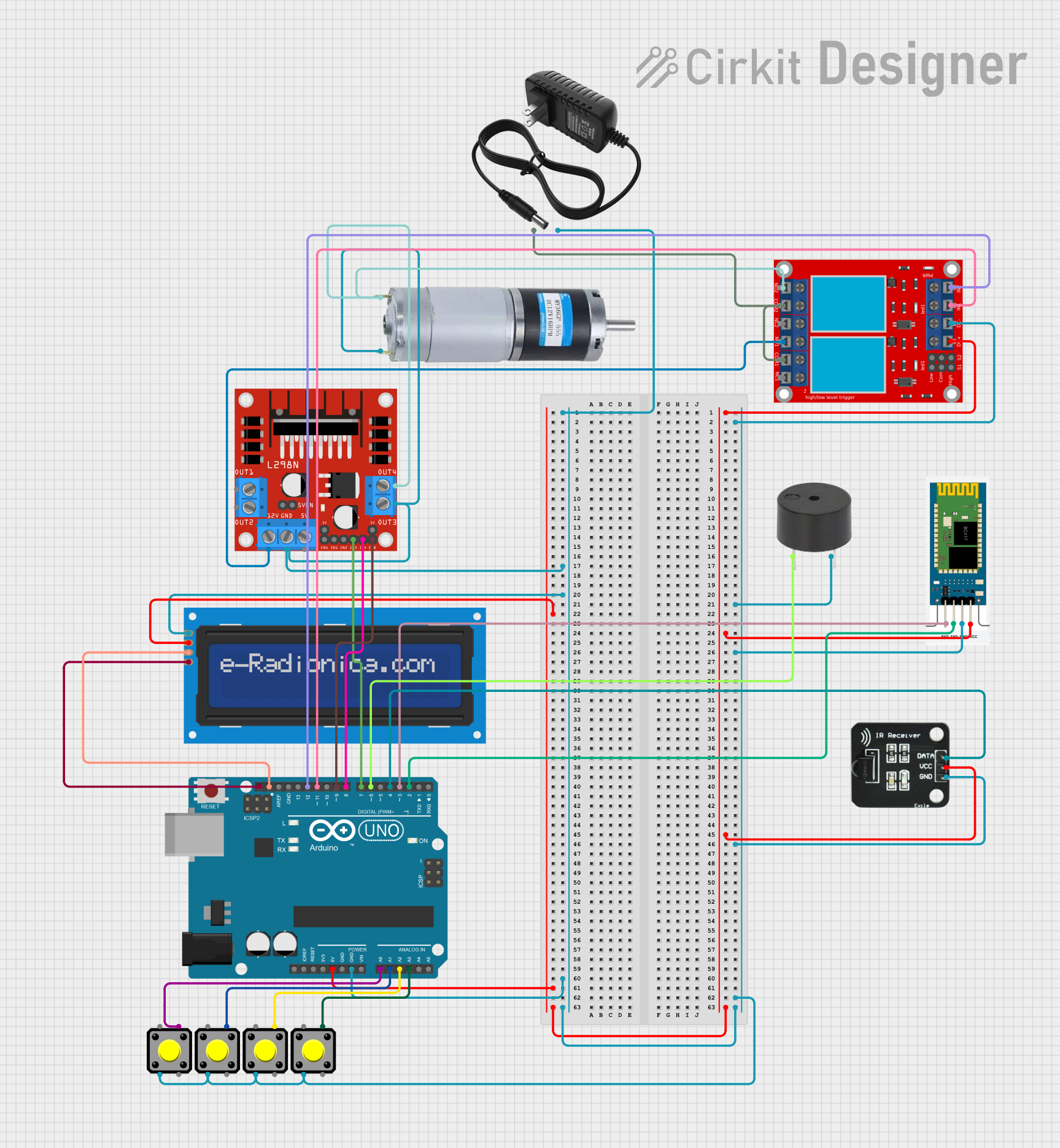
Circuit Documentation
Summary
This circuit is designed to control a centrifuge using an Arduino UNO. The system includes an LCD screen for displaying information, a Bluetooth module for wireless communication, an IR receiver for remote control, a DC motor driver for controlling the motor, a relay module for switching, and a buzzer for alerts. The circuit also includes multiple pushbuttons for user input.
Component List
Arduino UNO
- Description: Microcontroller board based on the ATmega328P.
- Pins: UNUSED, IOREF, Reset, 3.3V, 5V, GND, Vin, A0, A1, A2, A3, A4, A5, SCL, SDA, AREF, D13, D12, D11, D10, D9, D8, D7, D6, D5, D4, D3, D2, D1, D0
HC-06
- Description: Bluetooth module for wireless communication.
- Pins: RXD, TXD, GND, VCC
LCD screen 16x2 I2C
- Description: 16x2 character LCD display with I2C interface.
- Pins: SCL, SDA, VCC, GND
DC Motor
- Description: DC motor for driving the centrifuge.
- Pins: positive, negative
2 Channel Relay Module
- Description: Relay module for switching high-power devices.
- Pins: N.O. 2, COM 2, N.C. 2, N.O. 1, COM 1, N.C. 1, pin 7, pin 8, pin 9, pin 10, pin 11, pin 12, VCC+, VCC- (GND), IN 1, IN 2
Buzzer
- Description: Buzzer for audio alerts.
- Pins: PIN, GND
IR Receiver
- Description: Infrared receiver for remote control.
- Pins: DATA, VCC, GND
L298N DC Motor Driver
- Description: Motor driver module for controlling the DC motor.
- Pins: OUT1, OUT2, 12V, GND, 5V, OUT3, OUT4, 5V-ENA-JMP-I, 5V-ENA-JMP-O, +5V-J1, +5V-J2, ENA, IN1, IN2, IN3, IN4, ENB
Pushbutton
- Description: Pushbutton for user input.
- Pins: Pin 2, Pin 1, Pin 3, Pin 4
12V Power Supply
- Description: Power supply providing 12V.
- Pins: +, -
Wiring Details
Arduino UNO
- GND: Connected to GND of 12V power supply, L298N DC motor driver, LCD screen, 2 channel relay module, buzzer, HC-06, IR Receiver, and all pushbuttons.
- 5V: Connected to VCC of LCD screen, HC-06, IR Receiver, and 2 channel relay module.
- A0: Connected to Pin 4 of a pushbutton.
- A1: Connected to Pin 4 of a pushbutton.
- A2: Connected to Pin 4 of a pushbutton.
- A3: Connected to Pin 4 of a pushbutton.
- SCL: Connected to SCL of LCD screen.
- SDA: Connected to SDA of LCD screen.
- D12: Connected to IN 2 of 2 channel relay module.
- D11: Connected to IN 1 of 2 channel relay module.
- D9: Connected to ENB of L298N DC motor driver.
- D8: Connected to IN4 of L298N DC motor driver.
- D7: Connected to IN3 of L298N DC motor driver.
- D6: Connected to PIN of buzzer.
- D4: Connected to DATA of IR Receiver.
- D3: Connected to RXD of HC-06.
- D2: Connected to TXD of HC-06.
HC-06
- RXD: Connected to D3 of Arduino UNO.
- TXD: Connected to D2 of Arduino UNO.
- GND: Connected to GND of Arduino UNO.
- VCC: Connected to 5V of Arduino UNO.
LCD screen 16x2 I2C
- SCL: Connected to SCL of Arduino UNO.
- SDA: Connected to SDA of Arduino UNO.
- VCC: Connected to 5V of Arduino UNO.
- GND: Connected to GND of Arduino UNO.
DC Motor
- positive: Connected to OUT4 of L298N DC motor driver and N.O. 2 of 2 channel relay module.
- negative: Connected to GND of 12V power supply.
2 Channel Relay Module
- VCC+: Connected to 5V of Arduino UNO.
- VCC- (GND): Connected to GND of Arduino UNO.
- IN 1: Connected to D11 of Arduino UNO.
- IN 2: Connected to D12 of Arduino UNO.
- N.O. 1: Connected to 12V of L298N DC motor driver.
- N.O. 2: Connected to positive of DC motor.
- COM 1: Connected to + of 12V power supply.
- COM 2: Connected to COM 1.
Buzzer
- PIN: Connected to D6 of Arduino UNO.
- GND: Connected to GND of Arduino UNO.
IR Receiver
- DATA: Connected to D4 of Arduino UNO.
- VCC: Connected to 5V of Arduino UNO.
- GND: Connected to GND of Arduino UNO.
L298N DC Motor Driver
- GND: Connected to GND of 12V power supply.
- OUT3: Connected to GND of 12V power supply.
- OUT4: Connected to N.O. 2 of 2 channel relay module and positive of DC motor.
- 12V: Connected to N.O. 1 of 2 channel relay module.
- ENB: Connected to D9 of Arduino UNO.
- IN4: Connected to D8 of Arduino UNO.
- IN3: Connected to D7 of Arduino UNO.
Pushbuttons
- Pin 2: Connected to GND of Arduino UNO.
- Pin 4: Connected to A0, A1, A2, and A3 of Arduino UNO respectively.
12V Power Supply
- +: Connected to COM 1 of 2 channel relay module.
- -: Connected to GND of Arduino UNO, L298N DC motor driver, LCD screen, 2 channel relay module, buzzer, HC-06, IR Receiver, and all pushbuttons.
Code Documentation
#include <Wire.h>
#include <LiquidCrystal_I2C.h>
#include <SoftwareSerial.h>
#include <IRremote.h>

IRrecv receiver(4); // تم تغيير بن الاستقبال إلى 4
LiquidCrystal_I2C lcd(0x27, 16, 2);

// تعريف أزرار التحكم
#define bt_set    A3
#define bt_up     A2
#define bt_down   A1
#define bt_start  A0

// المتغيرات الخاصة بالوقت والسرعة
int time_s = 0;
int time_m = 0;
int set = 0;
bool timerRunning = false;
bool buzzerActive = false;
int speed = 5; // السرعة الأولية (5 إلى 8)

// منافذ البازر
int buzzer = 6;

// منافذ L298N للموتور
#define motorENA 9
#define motorIN1 7
#define motorIN2 8

// منافذ الريلاي
#define relayMotorDriver 11
#define relayMotor 10

unsigned long previousMillis = 0;
const long interval = 1000;

// إعداد الاتصال التسلسلي مع HC-05
SoftwareSerial btSerial(2, 3); // (RX, TX)

void setup() {
  pinMode(bt_set,   INPUT_PULLUP);
  pinMode(bt_up,    INPUT_PULLUP);
  pinMode(bt_down,  INPUT_PULLUP);
  pinMode(bt_start, INPUT_PULLUP);
  pinMode(buzzer, OUTPUT);

  // إعداد منافذ L298N
  pinMode(motorENA, OUTPUT);
  pinMode(motorIN1, OUTPUT);
  pinMode(motorIN2, OUTPUT);

  // إعداد اتجاه المحرك
  digitalWrite(motorIN1, HIGH);
  digitalWrite(motorIN2, LOW);

  // إعداد منافذ الريلاي
  pinMode(relayMotorDriver, OUTPUT);
  pinMode(relayMotor, OUTPUT);

  // تهيئة جهاز الاستقبال للأشعة تحت الحمراء