Cirkit Designer
Your all-in-one circuit design IDE
Home /
Project Documentation
Arduino-Controlled Obstacle-Avoiding Robot with Ultrasonic Sensor and IR Line Tracking

Circuit Documentation
Summary
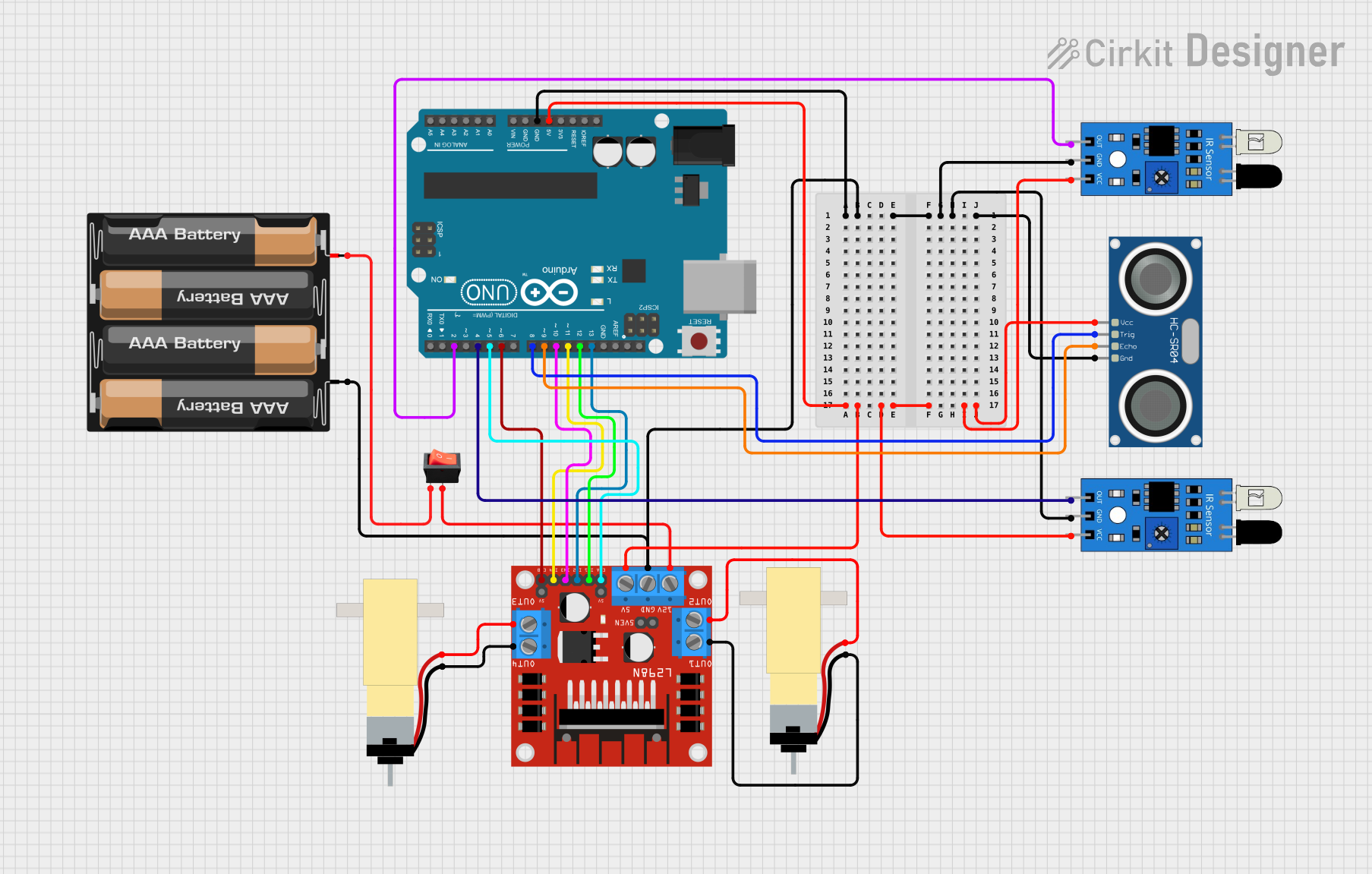
This circuit is designed to control a pair of DC motors using an Arduino UNO microcontroller in conjunction with an L298N DC motor driver. The system includes ultrasonic distance sensing via an HC-SR04 sensor and line detection using two infrared sensors. A 4 x AAA battery mount provides power, managed by a rocker switch. The Arduino UNO controls the motors based on distance measurements and line detection, adjusting the motor speeds and directions accordingly.
Component List
4 x AAA Battery Mount
- Description: A battery holder for four AAA batteries, providing power to the circuit.
- Purpose: Supplies the voltage necessary for the Arduino UNO and other components.
HC-SR04 Ultrasonic Sensor
- Description: An ultrasonic distance sensor that measures the distance to an object using sonar.
- Purpose: Provides distance measurements to the Arduino UNO for obstacle avoidance.
Arduino UNO
- Description: A microcontroller board based on the ATmega328P.
- Purpose: Acts as the central processing unit of the circuit, controlling sensor readings and motor operations.
IR Sensor
- Description: An infrared sensor capable of detecting the presence of objects or changes in surface reflectivity.
- Purpose: Used for line detection and navigation.
L298N DC Motor Driver
- Description: A motor driver module capable of driving two DC motors.
- Purpose: Controls the direction and speed of the motors based on commands from the Arduino UNO.
Rocker Switch
- Description: A simple on/off switch.
- Purpose: Allows manual power control to the motor driver and motors.
Hobby Gearmotor with 48:1 Gearbox
- Description: A DC motor with a gearbox for increased torque.
- Purpose: Provides the mechanical drive for the system's movement.
Wiring Details
4 x AAA Battery Mount
- Connections:
-to GND net+to rocker switch input
HC-SR04 Ultrasonic Sensor
- Connections:
VCCto 5V netGNDto GND netTRIGto Arduino UNO D8ECHOto Arduino UNO D9
Arduino UNO
- Connections:
GNDto GND net5Vto 5V net- Digital pins D2, D4, D5, D6, D8, D9, D10, D11, D12, D13 to various components as per the control logic
IR Sensor (Two Instances)
- Connections:
outto Arduino UNO D2 (first sensor) and D4 (second sensor)gndto GND netvccto 5V net
L298N DC Motor Driver
- Connections:
GNDto GND net5Vto 5V net12Vto rocker switch outputIN1to Arduino UNO D12IN2to Arduino UNO D13IN3to Arduino UNO D10IN4to Arduino UNO D11ENAto Arduino UNO D5ENBto Arduino UNO D6OUT1to motor 1 pin 1OUT2to motor 1 pin 2OUT3to motor 2 pin 2OUT4to motor 2 pin 1
Rocker Switch
- Connections:
inputto battery mount+outputto L298N DC motor driver12V
Hobby Gearmotor with 48:1 Gearbox (Two Instances)
- Connections:
- Motor 1
pin 1to L298N DC motor driverOUT1 - Motor 1
pin 2to L298N DC motor driverOUT2 - Motor 2
pin 1to L298N DC motor driverOUT4 - Motor 2
pin 2to L298N DC motor driverOUT3
- Motor 1
Documented Code
// Definición pines EnA y EnB para el control de la velocidad
int VelocidadMotor1 = 6;
int VelocidadMotor2 = 5;

// Definición de los pines de control de giro de los motores In1, In2, In3 e In4
int Motor1A = 13;
int Motor1B = 12;
int Motor2C = 11;
int Motor2D = 10;

// Sensores infrarrojo - izquierdo y derecho
int infraPin  = 2;
int infraPin1 = 4;

// Variables para la captura de los valores: 0 - fondo claro y 1 - línea negra
int valorInfra = 0;
int valorInfra1 = 0;

// Ultrasonicos
#define PIN_TRIG 9
#define PIN_ECHO 8

long duration, distancia;
// Configuración inicial
void setup() {
  Serial.begin(9600);

  delay(1000);
  //configuración del ultrasonico
  pinMode(PIN_TRIG, OUTPUT);
  pinMode(PIN_ECHO, INPUT);
  // Establecemos modo de los pines de los sensores infrarrojo
  pinMode(infraPin, INPUT);
  pinMode(infraPin1, INPUT);

  // Establecemos modo de los pines del control de motores
  pinMode(Motor1A,OUTPUT);
  pinMode(Motor1B,OUTPUT);
  pinMode(Motor2C,OUTPUT);
  pinMode(Motor2D,OUTPUT);
  pinMode(VelocidadMotor1, OUTPUT);
  pinMode(VelocidadMotor2, OUTPUT);

  // Configuramos los dos motores a velocidad 150/255
  analogWrite(VelocidadMotor1, 150);
  analogWrite(VelocidadMotor2, 180);

  // Configuramos sentido de giro
  digitalWrite(Motor1A, LOW);
  digitalWrite(Motor1B, LOW);
  digitalWrite(Motor2C, LOW);
  digitalWrite(Motor2D, LOW);
}

// Ejecución contínua
void loop() {
  // Ultrasonico: Primero, generar un pulso corto de 2-5 microsegundos.
  digitalWrite(PIN_TRIG, LOW);
  delayMicroseconds(5);
  digitalWrite(PIN_TRIG, HIGH);
  // Después de ajustar un nivel de señal alto, esperamos unos 10 microsegundos. En este punto el sensor enviará señales con una frecuencia de 40 kHz.
  delayMicroseconds(10);
  digitalWrite(PIN_TRIG, LOW);
  // Tiempo de retardo de la señal acústica en el sonar.
  duration = pulseIn(PIN_ECHO, HIGH);
  // Ahora es el momento de convertir el tiempo a distancia
  distancia = (duration / 2) / 29.1;
  Serial.print("Distancia al objeto: ");
  Serial.print(distancia);
  Serial.println(" см.");

  // Leemos el valor de los infrarrojo: 0 - fondo claro y 1 - línea negra
  valorInfra = digitalRead(infraPin);
  valorInfra1 = digitalRead(infraPin1);

  Serial.println(valorInfra);
  Serial.println(valorInfra1);
  if (distancia > 10){ //mientras no detecte nada a cierta distancia no se detiene
      // Cuatro escenarios: De frente
      if(valorInfra == 0 && valorInfra1 == 0){
        Serial.println("Ninguno en linea");

        // Modificamos sentido de giro de los motores
        digitalWrite(Motor1A, HIGH);
        digitalWrite(Motor2D, HIGH);
        delay(20);
        digitalWrite(Motor1A, LOW);
        digitalWrite(Motor2D,LOW);
        delay(20);
      }

      // El robot encuentra línea negra con el infrarrojo derecho y hay que corregir girando a la derecha
      if(valorInfra == 0 && valorInfra1 == 1){
        Serial.println("Derecho en linea");

        // Modificamos sentido de giro de los motores
        digitalWrite(Motor1A, LOW);
        digitalWrite(Motor2D,LOW);
        delay(25);
        digitalWrite(Motor1A, HIGH);
        digitalWrite(Motor2D,LOW);
        delay(20);
      }

      // El robot encuentra línea negra con el infrarrojo izquierdo y hay que corregir girando a la izquierda
      if(valorInfra == 1 && valorInfra1 == 0){
        Serial.println("Izquierdo en linea");

        // Modificamos sentido de giro de los motores
        digitalWrite(Motor1A,LOW);
        digitalWrite(Motor