
Circuit Documentation
Summary
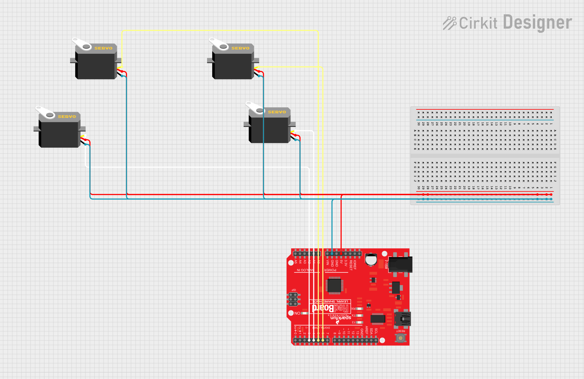
The circuit in question is designed to control multiple servo motors using a SparkFun RedBoard, which is Arduino-compatible. The RedBoard provides power and control signals to the servos. Each servo motor is connected to the RedBoard with three connections: power (VCC), ground (GND), and control signal (Pulse). The control signals for the servos are generated by the RedBoard's PWM-capable digital pins.
Component List
SparkFun RedBoard
- Description: An Arduino-compatible microcontroller board based on the ATmega328.
- Purpose: Acts as the central controller for the circuit, providing power and PWM signals to the servo motors.
- Pins Used:
- GND
- 5V
- D3 PWM
- D4
- D5 PWM
- D6 PWM
Servo Motors
- Description: Rotary actuators that allow for precise control of angular position.
- Purpose: To perform mechanical actions as instructed by the control signals from the RedBoard.
- Pins Used:
- GND
- VCC
- Pulse
Wiring Details
SparkFun RedBoard
- 5V: Connected to the VCC pin of all servo motors to provide power.
- GND: Connected to the GND pin of all servo motors to complete the power circuit.
- D3 PWM: Connected to the Pulse pin of one servo motor for control.
- D4: Connected to the Pulse pin of another servo motor for control.
- D5 PWM: Connected to the Pulse pin of another servo motor for control.
- D6 PWM: Connected to the Pulse pin of another servo motor for control.
Servo Motors
- Servo 1:
- VCC: Connected to the 5V output from the RedBoard.
- GND: Connected to the GND on the RedBoard.
- Pulse: Connected to D3 PWM on the RedBoard for control signal.
- Servo 2:
- VCC: Connected to the 5V output from the RedBoard.
- GND: Connected to the GND on the RedBoard.
- Pulse: Connected to D4 on the RedBoard for control signal.
- Servo 3:
- VCC: Connected to the 5V output from the RedBoard.
- GND: Connected to the GND on the RedBoard.
- Pulse: Connected to D5 PWM on the RedBoard for control signal.
- Servo 4:
- VCC: Connected to the 5V output from the RedBoard.
- GND: Connected to the GND on the RedBoard.
- Pulse: Connected to D6 PWM on the RedBoard for control signal.
Documented Code
No code was provided for the microcontrollers in the circuit. To control the servo motors, code would typically be written to generate PWM signals on the digital pins connected to the Pulse pins of the servos. This code would be uploaded to the SparkFun RedBoard using an appropriate development environment, such as the Arduino IDE.
The typical structure of the code would include setting up the PWM pins in the setup() function and then generating the control signals in the loop() function. Since no specific code is available, below is a generic example of how the code might look for controlling a single servo:
#include <Servo.h>

Servo myservo;  // create servo object to control a servo

void setup() {
  myservo.attach(3);  // attaches the servo on pin 3 to the servo object
}

void loop() {
  myservo.write(90);  // sets the servo position according to the scaled value
  delay(15);          // waits for the servo to get there
}
For the actual circuit, similar code would be replicated for each servo, with the attach() function referencing the appropriate pin connected to each servo's Pulse pin.