
Arduino Mega-Controlled Multi-Axis Stepper Motor System with Joystick Interface
View and Edit Project In Cirkit Designer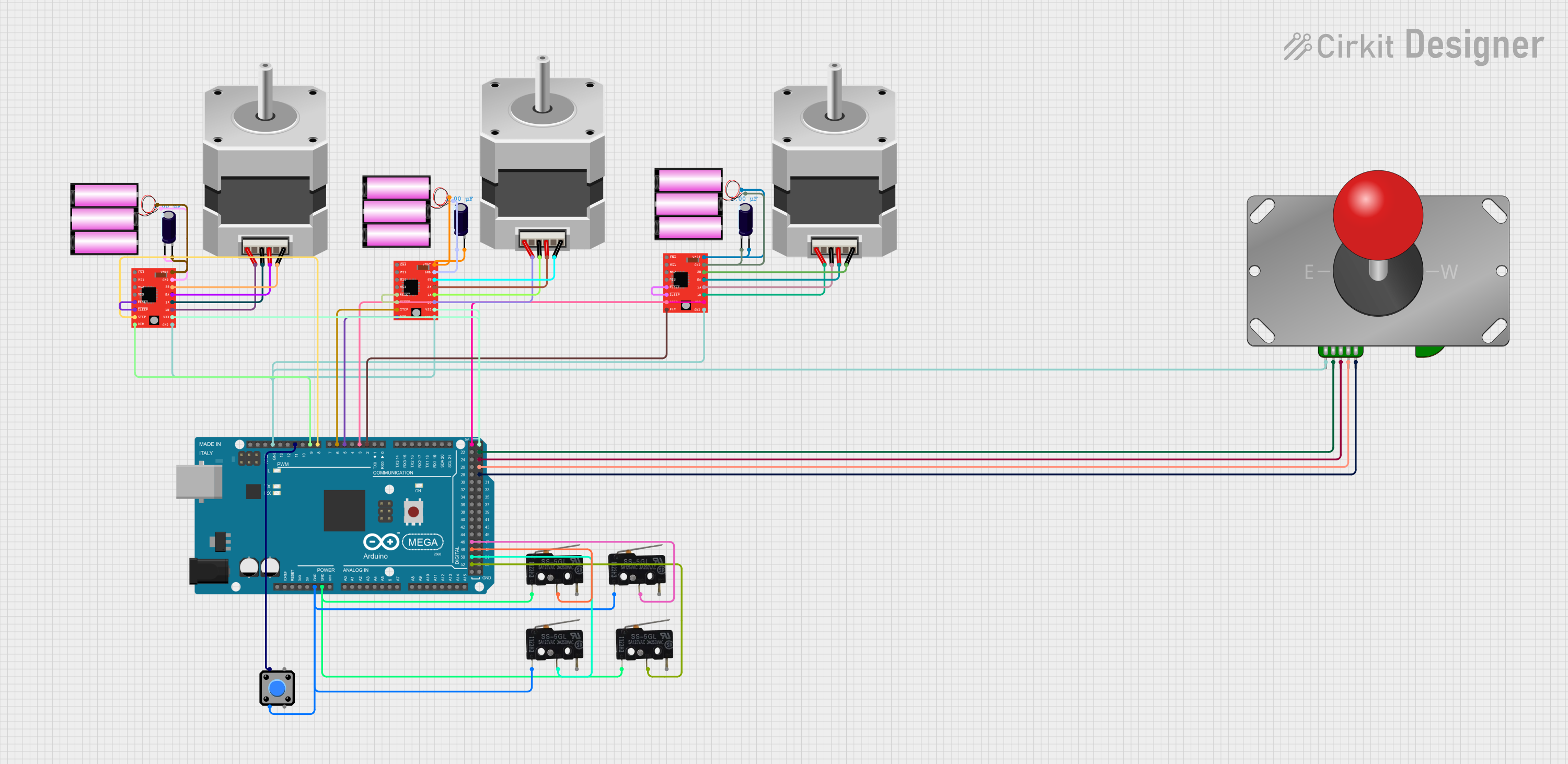
Circuit Documentation
Summary
This circuit is designed to control multiple stepper motors using A4988 stepper motor drivers, which are interfaced with an Arduino Mega 2560 microcontroller. The circuit includes electrolytic capacitors for voltage smoothing, micro switches for input, a pushbutton, and an Adafruit Arcade Joystick for manual control. The power supply for the motor drivers is provided by 12V batteries. The circuit appears to be part of a larger system, potentially for a robotics or automation project, where precise motor control is required.
Component List
Electrolytic Capacitors
- Description: Used for voltage smoothing on the power supply lines to the A4988 stepper motor drivers.
- Properties: Capacitance: 1 µF (microfarads)
A4988 Stepper Motor Drivers (Red)
- Description: These modules control the stepper motors based on signals from the Arduino Mega 2560.
- Pins: ENABLE, MS1, MS2, MS3, RESET, SLEEP, STEP, DIR, VMOT, GND, 2B, 2A, 1A, 1B, VDD
Stepper Motors (Bipolar)
- Description: Actuators that convert digital pulses into mechanical shaft rotation.
- Pins: D, B, C, A
Micro Switches
- Description: Switches that may be used as limit switches or for user input.
- Pins: COM, NO, NC
Pushbutton
- Description: A simple pushbutton for user input.
- Pins: Pin 2, Pin 1, Pin 3, Pin 4
Adafruit Arcade Joystick
- Description: A joystick for manual control, likely used to control the movement of the stepper motors.
- Pins: COM, N, S, W, E
Arduino Mega 2560
- Description: The main microcontroller unit that controls the logic of the circuit.
- Pins: Multiple digital and analog I/O pins, power, and ground pins.
Batteries (12V)
- Description: Provide the power supply for the stepper motor drivers.
Wiring Details
Electrolytic Capacitors
- Connected between the VMOT and GND pins of the A4988 stepper motor drivers and the positive and negative terminals of the 12V batteries, respectively.
A4988 Stepper Motor Drivers (Red)
- VMOT connected to the positive terminal of a 12V battery through a capacitor.
- GND connected to the negative terminal of a 12V battery through a capacitor.
- RESET and SLEEP pins shorted together.
- STEP and DIR pins controlled by the Arduino Mega 2560.
- 2B, 2A, 1A, 1B pins connected to the corresponding pins on the stepper motors.
- VDD connected to the 5V output from the Arduino Mega 2560.
Stepper Motors (Bipolar)
- Connected to the A4988 stepper motor drivers.
Micro Switches
- COM pins connected to GND.
- NO pins connected to various digital I/O pins on the Arduino Mega 2560.
Pushbutton
- One side connected to GND, the other to a digital I/O pin on the Arduino Mega 2560.
Adafruit Arcade Joystick
- COM pin connected to GND.
- N, S, W, E pins connected to digital I/O pins on the Arduino Mega 2560.
Arduino Mega 2560
- Controls the A4988 stepper motor drivers, reads inputs from the micro switches and the joystick, and provides power to the motor drivers.
Batteries (12V)
- Provide power to the A4988 stepper motor drivers through the electrolytic capacitors.
Documented Code
void setup() {
  // put your setup code here, to run once:

}

void loop() {
  // put your main code here, to run repeatedly:

}
Note: The provided code is a template and does not contain any functional code. The user must implement the setup and loop functions to control the stepper motors, read inputs from the switches and joystick, and perform any other required tasks.