
Circuit Documentation
Summary
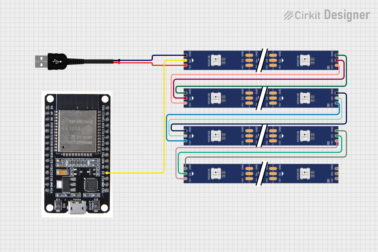
This circuit consists of an ESP32 microcontroller, a series of WS2812 RGB LED strips, and a USB male 2-pin connection for power. The ESP32 controls the LED strips, which are powered by the USB connection. The LED strips are connected in series, with the data output of one strip feeding into the data input of the next.
Component List
WS2812 RGB LED strip
- Description: Individually addressable RGB LED strip.
- Pins: DIN, 5V, GND, DO
USB male 2 pin connection
- Description: Provides power to the circuit.
- Pins: Positive +, Negative -
ESP32
- Description: Microcontroller used to control the LED strips.
- Pins: EN, VP, VN, D34, D35, D32, D33, D25, D26, D27, D14, D12, D13, GND, VIN, 3V3, D15, D2, D4, RX2, TX2, D5, D18, D19, D21, RX0, TX0, D22, D23, BOOT
Wiring Details
WS2812 RGB LED strip (1)
- DIN: Connected to D2 of ESP32
- 5V: Connected to Positive + of USB male 2 pin connection
- GND: Connected to Negative - of USB male 2 pin connection
- DO: Connected to DIN of WS2812 RGB LED strip (2)
WS2812 RGB LED strip (2)
- DIN: Connected to DO of WS2812 RGB LED strip (1)
- 5V: Connected to 5V of WS2812 RGB LED strip (1)
- GND: Connected to GND of WS2812 RGB LED strip (1)
- DO: Connected to DIN of WS2812 RGB LED strip (3)
WS2812 RGB LED strip (3)
- DIN: Connected to DO of WS2812 RGB LED strip (2)
- 5V: Connected to 5V of WS2812 RGB LED strip (2)
- GND: Connected to GND of WS2812 RGB LED strip (2)
- DO: Connected to DIN of WS2812 RGB LED strip (4)
WS2812 RGB LED strip (4)
- DIN: Connected to DO of WS2812 RGB LED strip (3)
- 5V: Connected to 5V of WS2812 RGB LED strip (3)
- GND: Connected to GND of WS2812 RGB LED strip (3)
USB male 2 pin connection
- Positive +: Connected to 5V of WS2812 RGB LED strip (1)
- Negative -: Connected to GND of WS2812 RGB LED strip (1)
ESP32
- D2: Connected to DIN of WS2812 RGB LED strip (1)
Code
No code provided for this circuit.