
Arduino UNO-Based Vibration Monitoring and Control System with ADXL345 and L298N Motor Driver
View and Edit Project In Cirkit Designer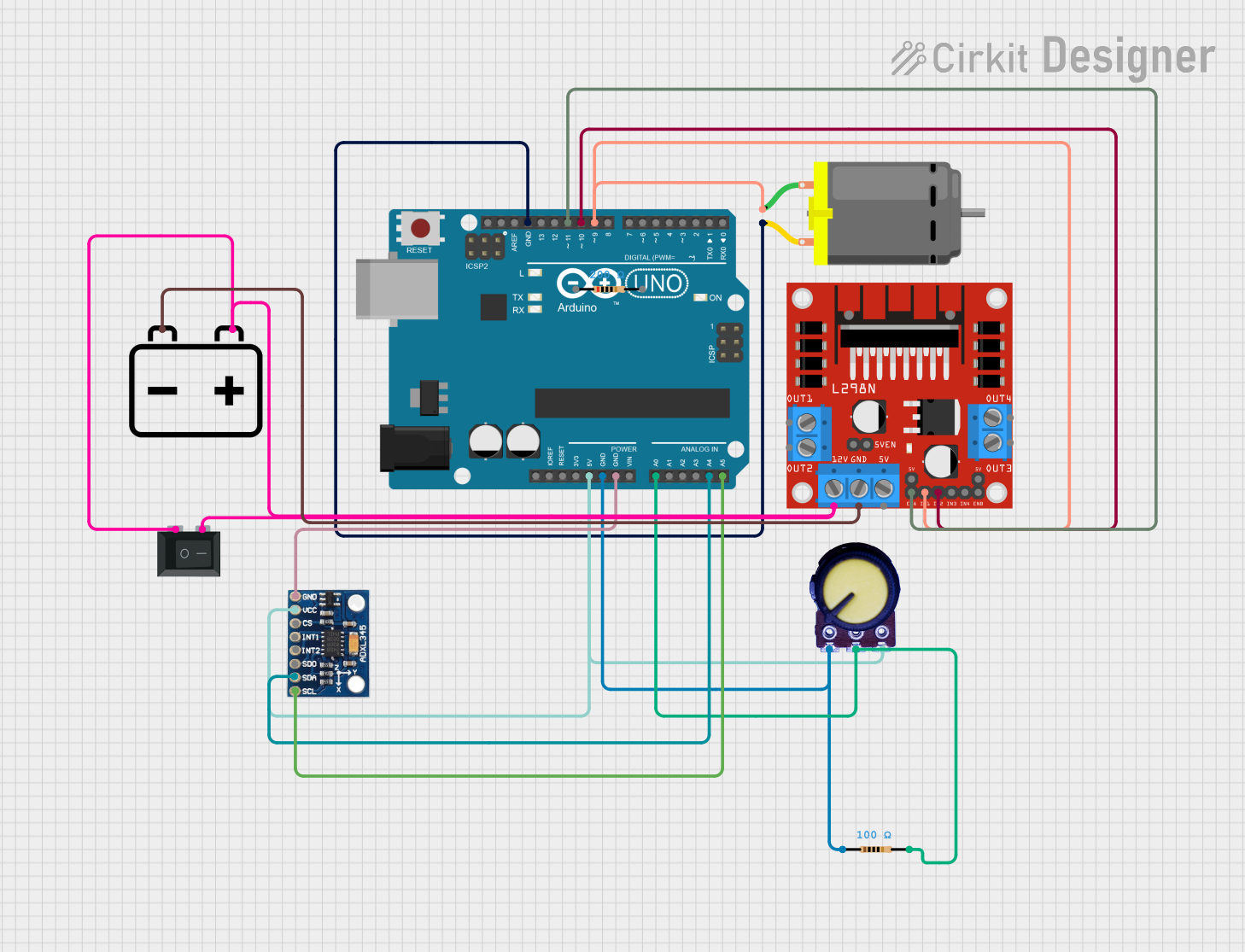
Circuit Documentation
Summary
This circuit is designed to control a vibrating table using an Arduino UNO, an L298N motor driver, a DC motor, a potentiometer, an ADXL345 accelerometer, and a 12V battery. The Arduino UNO reads vibration data from the ADXL345 accelerometer and adjusts the motor speed accordingly. The potentiometer allows manual control of the motor speed, and an emergency stop button is included for safety.
Component List
Arduino UNO
- Description: Microcontroller board based on the ATmega328P.
- Pins: UNUSED, IOREF, Reset, 3.3V, 5V, GND, Vin, A0, A1, A2, A3, A4, A5, SCL, SDA, AREF, D13, D12, D11, D10, D9, D8, D7, D6, D5, D4, D3, D2, D1, D0
L298N DC Motor Driver
- Description: Dual H-Bridge motor driver.
- Pins: OUT1, OUT2, 12V, GND, 5V, OUT3, OUT4, 5V-ENA-JMP-I, 5V-ENA-JMP-O, +5V-J1, +5V-J2, ENA, IN1, IN2, IN3, IN4, ENB
DC Motor
- Description: Standard DC motor.
- Pins: pin 1, pin 2
Potentiometer
- Description: Variable resistor used to control motor speed.
- Pins: GND, Output, VCC
ADXL345
- Description: 3-axis accelerometer.
- Pins: GND, VCC, CS, INT1, INT2, SDO, SDA, SCL
12V Battery
- Description: Power source for the motor driver.
- Pins: -, +
Rocker Switch (SPST)
- Description: Single-pole single-throw switch for emergency stop.
- Pins: 1, 2
Resistor (200 Ohms)
- Description: Resistor with 200 Ohms resistance.
- Pins: pin1, pin2
Resistor (100 Ohms)
- Description: Resistor with 100 Ohms resistance.
- Pins: pin1, pin2
Wiring Details
Arduino UNO
- 5V connected to VCC of ADXL345 and VCC of Potentiometer.
- GND connected to GND of ADXL345, GND of Potentiometer, pin1 of 100 Ohms Resistor, and pin 2 of DC Motor.
- A0 connected to Output of Potentiometer and pin2 of 100 Ohms Resistor.
- A4 connected to SDA of ADXL345.
- A5 connected to SCL of ADXL345.
- D11 connected to ENA of L298N DC Motor Driver.
- D10 connected to IN2 of L298N DC Motor Driver.
- D9 connected to pin 1 of DC Motor and IN1 of L298N DC Motor Driver.
L298N DC Motor Driver
- 12V connected to pin 1 and pin 2 of Rocker Switch and + of 12V Battery.
- GND connected to - of 12V Battery.
- ENA connected to D11 of Arduino UNO.
- IN2 connected to D10 of Arduino UNO.
- IN1 connected to D9 of Arduino UNO and pin 1 of DC Motor.
DC Motor
- pin 1 connected to D9 of Arduino UNO and IN1 of L298N DC Motor Driver.
- pin 2 connected to GND of Arduino UNO.
Potentiometer
- GND connected to GND of Arduino UNO.
- Output connected to A0 of Arduino UNO and pin2 of 100 Ohms Resistor.
- VCC connected to 5V of Arduino UNO.
ADXL345
- GND connected to GND of Arduino UNO.
- VCC connected to 5V of Arduino UNO.
- SDA connected to A4 of Arduino UNO.
- SCL connected to A5 of Arduino UNO.
12V Battery
- + connected to pin 1 and pin 2 of Rocker Switch and 12V of L298N DC Motor Driver.
- - connected to GND of L298N DC Motor Driver.
Rocker Switch (SPST)
- pin 1 connected to pin 2 and 12V of L298N DC Motor Driver and + of 12V Battery.
- pin 2 connected to pin 1 and 12V of L298N DC Motor Driver and + of 12V Battery.
Resistor (200 Ohms)
- pin1 connected to GND of Arduino UNO.
- pin2 connected to A0 of Arduino UNO and Output of Potentiometer.
Resistor (100 Ohms)
- pin1 connected to GND of Arduino UNO.
- pin2 connected to A0 of Arduino UNO and Output of Potentiometer.
Code Documentation
#include <Wire.h>
#include <Adafruit_SSD1306.h> // Install via Library Manager

// Define ADXL345 I2C address
#define ADXL345_ADDR 0x53

// OLED display configuration
#define SCREEN_WIDTH 128
#define SCREEN_HEIGHT 64
Adafruit_SSD1306 display(SCREEN_WIDTH, SCREEN_HEIGHT, &Wire, -1);

// L298N motor driver pins
const int motorIn1 = 7;
const int motorIn2 = 8;
const int motorENA = 6;

// Potentiometer pin
const int potPin = A0;

// Emergency stop button pin
const int stopButtonPin = 2;

// LED indicators
const int greenLED = 10; // Normal vibration
const int redLED = 11;   // Excessive vibration

// Vibration thresholds
const float vibrationMinThreshold = 1000.0;
const float vibrationMaxThreshold = 8000.0;

// Variables for vibration monitoring
int16_t ax, ay, az;  // Acceleration values
float vibrationMagnitude = 0;
bool motorEnabled = true;

void setup() {
  // Initialize Serial Monitor
  Serial.begin(9600);

  // Initialize I2C communication
  Wire.begin();
  setupADXL345();

  // Set L298N motor driver pins as output
  pinMode(motorIn1, OUTPUT);
  pinMode(motorIn2, OUTPUT);
  pinMode(motorENA, OUTPUT);

  // Configure emergency stop button
  pinMode(stopButtonPin, INPUT_PULLUP);

  // Configure LED indicators
  pinMode(greenLED, OUTPUT);
  pinMode(redLED, OUTPUT);

  // Initialize OLED display
  if ( !display.begin(SSD1306_SWITCHCAPVCC, 0x3C)){

    Serial.println("OLED initialization failed!");
    while (1); // Stop here if OLED fails
  }
  display.clearDisplay();
  display.display();

  Serial.println("Vibrating Table Initialized");
}

void loop() {
  // Check emergency stop button
  if (digitalRead(stopButtonPin) == LOW) {
    motorEnabled = false; // Disable motor
    stopMotor();
    displayMessage("Emergency Stop!");
    delay(500);
    return;
  } else {
    motorEnabled = true;
  }

  // Read accelerometer data
  readADXL345(ax, ay, az);

  // Calculate vibration magnitude (RMS)
  vibrationMagnitude = sqrt(sq(ax) + sq(ay) + sq(az));

  // Read potentiometer value to control motor speed
  int potValue = analogRead(potPin);
  int motorSpeed = map(potValue, 0, 1023, 0, 255);

  // Adjust motor speed dynamically based on vibration thresholds
  if (vibrationMagnitude < vibrationMinThreshold) {
    motorSpeed = constrain(motorSpeed + 50, 0, 255); // Increase speed
    digitalWrite(greenLED, HIGH);
    digitalWrite(redLED, LOW);
  } else if (vibrationMagnitude > vibrationMaxThreshold) {
    motorSpeed = constrain(motorSpeed - 50, 0, 255); // Decrease speed
    digitalWrite(greenLED, LOW);
    digitalWrite(redLED, HIGH);
  } else {
    digitalWrite(greenLED, HIGH);
    digitalWrite(redLED, LOW);
  }

  // Control motor speed with PWM
  if (motorEnabled) {