Arduino UNO Based Multi-Sensor Data Logger
Circuit Documentation
Summary
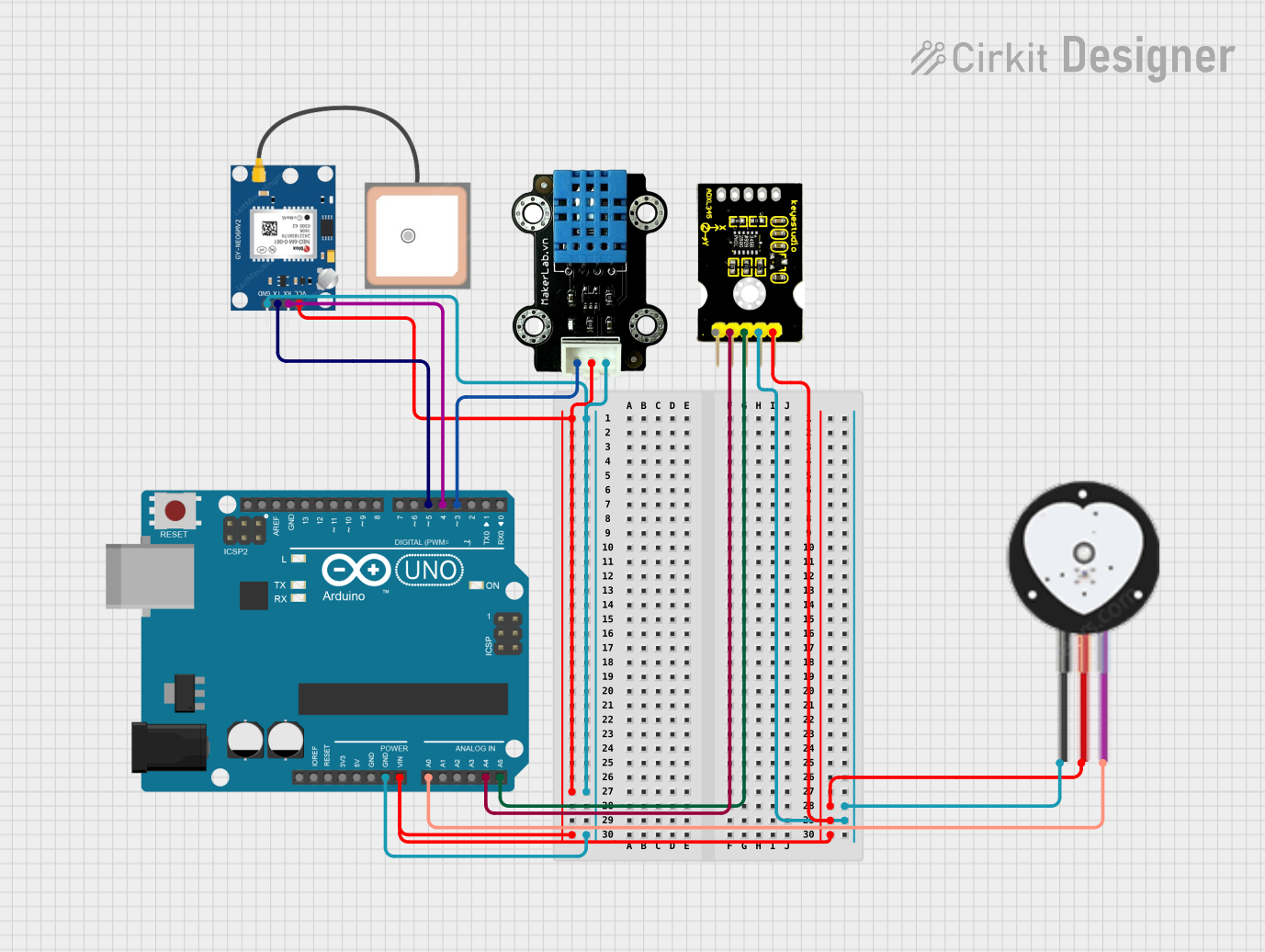
This circuit integrates various sensors and modules with an Arduino UNO microcontroller to perform multiple functions including temperature and humidity sensing, acceleration measurement, heart rate monitoring, and GPS data reception. The Arduino UNO serves as the central processing unit, interfacing with a DHT11 temperature and humidity sensor, an ADXL345 accelerometer, a GPS NEO 6M module, and a heart pulse sensor. The circuit is designed to read data from these sensors and output the information through the Arduino's serial interface.
Component List
Arduino UNO
- Microcontroller board based on the ATmega328P
- It has 14 digital input/output pins, 6 analog inputs, a USB connection, a power jack, an ICSP header, and a reset button.
MKE-S14 DHT11 Temperature And Humidity Sensor
- A basic, ultra low-cost digital temperature and humidity sensor.
- It uses a capacitive humidity sensor and a thermistor to measure the surrounding air and outputs a digital signal on the data pin.
GPS NEO 6M
- A GPS module that communicates over serial with the ability to provide location data.
- It operates on a voltage of 3.3V to 5V and has a battery for power backup and EEPROM for storing configuration settings.
ADXL345 Keystudio
- A small, thin, low power, 3-axis accelerometer with high resolution (13-bit) measurement.
- It measures the static acceleration of gravity in tilt-sensing applications, as well as dynamic acceleration resulting from motion or shock.
Heart Pulse Sensor
- A plug-and-play heart-rate sensor for Arduino.
- It can be used by students, artists, athletes, makers, and game & mobile developers who want to easily incorporate live heart-rate data into their projects.
Wiring Details
Arduino UNO
- GND connected to the ground pins of all other components.
- Vin connected to the 5V pins of all other components.
- A0 connected to the SIGNAL pin of the Heart Pulse Sensor.
- A4 (SDA) connected to the SDA pin of the ADXL345 Keystudio.
- A5 (SCL) connected to the SCL pin of the ADXL345 Keystudio.
- D3 connected to the SIG pin of the DHT11 Temperature And Humidity Sensor.
- D4 connected to the RX pin of the GPS NEO 6M.
- D5 connected to the TX pin of the GPS NEO 6M.
MKE-S14 DHT11 Temperature And Humidity Sensor
- SIG connected to the D3 pin of the Arduino UNO.
- 5V connected to the Vin pin of the Arduino UNO.
- GND connected to the GND pin of the Arduino UNO.
GPS NEO 6M
- VCC connected to the Vin pin of the Arduino UNO.
- RX connected to the D4 pin of the Arduino UNO.
- TX connected to the D5 pin of the Arduino UNO.
- GND connected to the GND pin of the Arduino UNO.
ADXL345 Keystudio
- SDA connected to the A4 pin of the Arduino UNO.
- SCL connected to the A5 pin of the Arduino UNO.
- GND connected to the GND pin of the Arduino UNO.
- 5V connected to the Vin pin of the Arduino UNO.
Heart Pulse Sensor
- SIGNAL connected to the A0 pin of the Arduino UNO.
- VCC connected to the Vin pin of the Arduino UNO.
- GND connected to the GND pin of the Arduino UNO.
Documented Code
#include <Wire.h>
#include <Adafruit_Sensor.h>
#include <Adafruit_ADXL345_U.h>
#include <DHT.h>
#include <SoftwareSerial.h>

// Pin definitions
#define HEARTBEAT_PIN A0
#define DHT_PIN 3
#define GPS_RX_PIN 4
#define GPS_TX_PIN 5

// DHT11 setup
#define DHTTYPE DHT11
DHT dht(DHT_PIN, DHTTYPE);

// ADXL345 setup
Adafruit_ADXL345_Unified accel = Adafruit_ADXL345_Unified(12345);

// GPS setup
SoftwareSerial gpsSerial(GPS_RX_PIN, GPS_TX_PIN);

void setup() {
  Serial.begin(9600);
  gpsSerial.begin(9600);
  dht.begin();
  if (!accel.begin()) {
    Serial.println("No ADXL345 detected!");
    while (1);
  }
  Serial.println("Setup complete.");
}

void loop() {
  // Read heartbeat sensor
  int heartbeat = analogRead(HEARTBEAT_PIN);
  Serial.print("Heartbeat: ");
  Serial.println(heartbeat);

  // Read DHT11 sensor
  float h = dht.readHumidity();
  float t = dht.readTemperature();
  Serial.print("Humidity: ");
  Serial.print(h);
  Serial.print(" %\t");
  Serial.print("Temperature: ");
  Serial.print(t);
  Serial.println(" *C");

  // Read ADXL345 sensor
  sensors_event_t event;
  accel.getEvent(&event);
  Serial.print("X: ");
  Serial.print(event.acceleration.x);
  Serial.print(" \tY: ");
  Serial.print(event.acceleration.y);
  Serial.print(" \tZ: ");
  Serial.print(event.acceleration.z);
  Serial.println(" m/s^2");

  // Read GPS data
  while (gpsSerial.available()) {
    char c = gpsSerial.read();
    Serial.print(c);
  }

  delay(2000); // Delay for 2 seconds
}
This code initializes and reads data from the connected sensors, then outputs the readings through the Arduino's serial interface. It includes setup and loop functions that are standard in Arduino programming. The setup() function initializes the serial communication, the sensors, and checks for the presence of the ADXL345 accelerometer. The loop() function reads data from the heart pulse sensor, DHT11 sensor, ADXL345 accelerometer, and GPS module, then prints the data to the serial monitor every two seconds.