Cirkit Designer
Your all-in-one circuit design IDE
Home /
Project Documentation
Arduino UNO-Based Battery-Powered Robotic Vehicle with Ultrasonic Sensor and Servo Control
Circuit Documentation
Summary
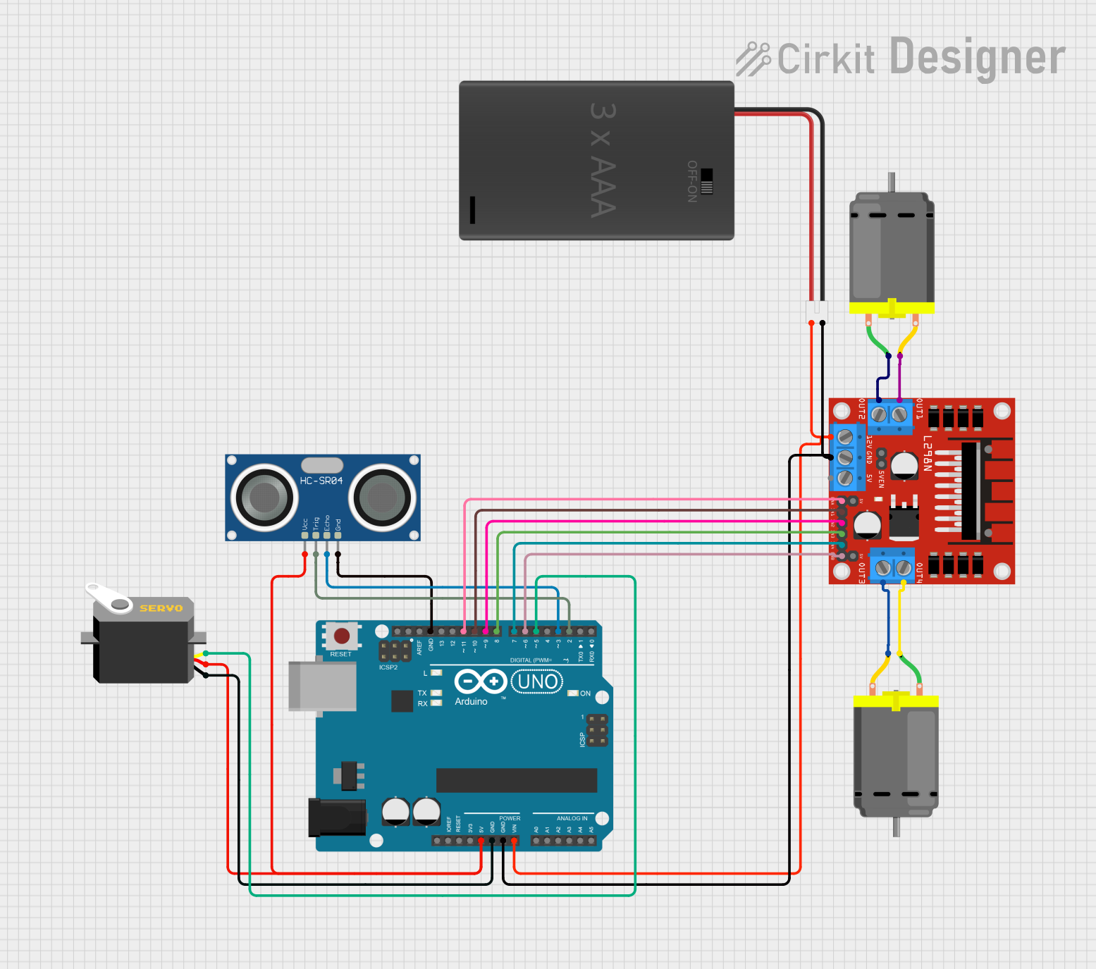
This document provides a detailed overview of a circuit that includes an Arduino UNO, two DC motors, an L298N DC motor driver, an HC-SR04 Ultrasonic Sensor, a Servo, and a 3xAAA Battery Pack with Switch and JST. The circuit is designed to control the motors and servo, and to measure distance using the ultrasonic sensor. The Arduino UNO serves as the main microcontroller, orchestrating the operations of the connected components.
Component List
Arduino UNO
- Description: A microcontroller board based on the ATmega328P.
- Pins: UNUSED, IOREF, Reset, 3.3V, 5V, GND, Vin, A0, A1, A2, A3, A4, A5, SCL, SDA, AREF, D13, D12, D11, D10, D9, D8, D7, D6, D5, D4, D3, D2, D1, D0
DC Motor (Motor 1)
- Description: A simple DC motor.
- Pins: pin 1, pin 2
DC Motor (Motor 2)
- Description: A simple DC motor.
- Pins: pin 1, pin 2
L298N DC Motor Driver
- Description: A dual H-Bridge motor driver.
- Pins: OUT1, OUT2, 12V, GND, 5V, OUT3, OUT4, 5V-ENA-JMP-I, 5V-ENA-JMP-O, +5V-J1, +5V-J2, ENA, IN1, IN2, IN3, IN4, ENB
HC-SR04 Ultrasonic Sensor
- Description: An ultrasonic distance sensor.
- Pins: VCC, TRIG, ECHO, GND
Servo
- Description: A servo motor.
- Pins: gnd, vcc, pulse
3xAAA Battery Pack with Switch and JST
- Description: A battery pack with a switch and JST connector.
- Pins: POS, NEG
Wiring Details
Arduino UNO
- 5V connected to Servo (vcc) and HC-SR04 Ultrasonic Sensor (VCC)
- GND connected to Servo (gnd), 3xAAA Battery Pack with Switch and JST (NEG), L298N DC motor driver (GND), and HC-SR04 Ultrasonic Sensor (GND)
- Vin connected to 3xAAA Battery Pack with Switch and JST (POS) and L298N DC motor driver (12V)
- D11 connected to L298N DC motor driver (ENA)
- D10 connected to L298N DC motor driver (IN1)
- D9 connected to L298N DC motor driver (IN2)
- D8 connected to L298N DC motor driver (IN3)
- D7 connected to L298N DC motor driver (IN4)
- D6 connected to L298N DC motor driver (ENB)
- D5 connected to Servo (pulse)
- D3 connected to HC-SR04 Ultrasonic Sensor (ECHO)
- D2 connected to HC-SR04 Ultrasonic Sensor (TRIG)
DC Motor (Motor 1)
- pin 1 connected to L298N DC motor driver (OUT2)
- pin 2 connected to L298N DC motor driver (OUT1)
DC Motor (Motor 2)
- pin 1 connected to L298N DC motor driver (OUT4)
- pin 2 connected to L298N DC motor driver (OUT3)
L298N DC Motor Driver
- OUT1 connected to DC Motor (Motor 1) (pin 2)
- OUT2 connected to DC Motor (Motor 1) (pin 1)
- OUT3 connected to DC Motor (Motor 2) (pin 2)
- OUT4 connected to DC Motor (Motor 2) (pin 1)
- 12V connected to Arduino UNO (Vin) and 3xAAA Battery Pack with Switch and JST (POS)
- GND connected to Arduino UNO (GND) and 3xAAA Battery Pack with Switch and JST (NEG)
- ENA connected to Arduino UNO (D11)
- IN1 connected to Arduino UNO (D10)
- IN2 connected to Arduino UNO (D9)
- IN3 connected to Arduino UNO (D8)
- IN4 connected to Arduino UNO (D7)
- ENB connected to Arduino UNO (D6)
HC-SR04 Ultrasonic Sensor
- VCC connected to Arduino UNO (5V)
- TRIG connected to Arduino UNO (D2)
- ECHO connected to Arduino UNO (D3)
- GND connected to Arduino UNO (GND)
Servo
- vcc connected to Arduino UNO (5V)
- gnd connected to Arduino UNO (GND)
- pulse connected to Arduino UNO (D5)
3xAAA Battery Pack with Switch and JST
- POS connected to Arduino UNO (Vin) and L298N DC motor driver (12V)
- NEG connected to Arduino UNO (GND) and L298N DC motor driver (GND)
Documented Code
Arduino UNO Code
void setup() {
  // put your setup code here, to run once:

}

void loop() {
  // put your main code here, to run repeatedly:

}
Servo Code
void setup() {
  // put your setup code here, to run once:

}

void loop() {
  // put your main code here, to run repeatedly:

}
3xAAA Battery Pack with Switch and JST Code
void setup() {
  // put your setup code here, to run once:

}

void loop() {
  // put your main code here, to run repeatedly:

}
This documentation provides a comprehensive overview of the circuit, including the components used, their wiring details, and the code for the microcontrollers.