Cirkit Designer
Your all-in-one circuit design IDE
Home /
Project Documentation
Arduino Mega 2560-Based RFID Access Control System with LCD Display and Buzzer
Circuit Documentation
Summary
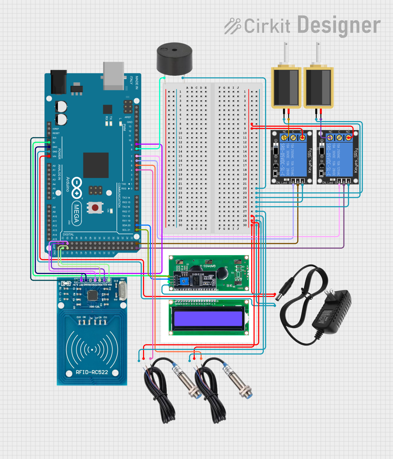
This circuit is designed to control access using RFID cards, an LCD display, and solenoids. It includes an Arduino Mega 2560 microcontroller, RFID reader, LCD display, relays, solenoids, inductive sensors, and a buzzer. The system allows authorized users to unlock doors using RFID cards and provides feedback via the LCD and buzzer.
Component List
1-Channel Relay (5V 10A)
- Pins: NC, signal, C, power, NO, ground
- Description: Used to control high-power devices like solenoids.
Inductive Sensor
- Pins: Signal, VCC, GND
- Description: Detects the presence of metal objects.
Solenoid
- Pins: pin1, pin2
- Description: Electromechanical device used to lock/unlock doors.
12V Power Supply
- Pins: +, -
- Description: Provides 12V power to the circuit.
RFID-RC522
- Pins: VCC (3.3V), RST, GND, IRQ, MISO, MOSI, SCK, SDA
- Description: RFID reader module for reading RFID cards.
LCD I2C
- Pins: GND, VCC, SDA, SCL
- Description: LCD display with I2C interface for displaying messages.
Arduino Mega 2560
- Pins: IOREF, RESET, 3V3, 5V, GND, VIN, A0-A15, D0-D53, AREF, SDA, SCL
- Description: Microcontroller used to control the entire system.
Buzzer
- Pins: PIN, GND
- Description: Provides audible feedback.
Wiring Details
1-Channel Relay (5V 10A)
- NO: Connected to NO of the other relay, VCC of both inductive sensors, + of the 12V power supply, and VIN of the Arduino Mega 2560.
- ground: Connected to GND of the buzzer, pin1 of both solenoids, ground of the other relay, GND of both inductive sensors, GND of the LCD I2C, - of the 12V power supply, and GND of the Arduino Mega 2560.
- signal: Connected to D6 PWM of the Arduino Mega 2560.
- power: Connected to 5V of the Arduino Mega 2560.
Inductive Sensor
- Signal: Connected to D4 PWM and D5 PWM of the Arduino Mega 2560.
- VCC: Connected to NO of both relays, + of the 12V power supply, and VIN of the Arduino Mega 2560.
- GND: Connected to GND of the buzzer, pin1 of both solenoids, ground of both relays, GND of the LCD I2C, - of the 12V power supply, and GND of the Arduino Mega 2560.
Solenoid
- pin1: Connected to GND of the buzzer, ground of both relays, GND of both inductive sensors, GND of the LCD I2C, - of the 12V power supply, and GND of the Arduino Mega 2560.
- pin2: Connected to NC of both relays.
12V Power Supply
- +: Connected to NO of both relays, VCC of both inductive sensors, and VIN of the Arduino Mega 2560.
- -: Connected to GND of the buzzer, pin1 of both solenoids, ground of both relays, GND of both inductive sensors, GND of the LCD I2C, and GND of the Arduino Mega 2560.
RFID-RC522
- VCC (3.3V): Connected to 3V3 of the Arduino Mega 2560.
- GND: Connected to GND of the Arduino Mega 2560.
- RST: Connected to D9 PWM of the Arduino Mega 2560.
- SCK: Connected to D52 of the Arduino Mega 2560.
- MISO: Connected to D50 of the Arduino Mega 2560.
- MOSI: Connected to D51 of the Arduino Mega 2560.
- SDA: Connected to D53 of the Arduino Mega 2560.
LCD I2C
- GND: Connected to GND of the buzzer, pin1 of both solenoids, ground of both relays, GND of both inductive sensors, - of the 12V power supply, and GND of the Arduino Mega 2560.
- VCC: Connected to 5V of the Arduino Mega 2560.
- SCL: Connected to D21/SCL of the Arduino Mega 2560.
- SDA: Connected to D20/SDA of the Arduino Mega 2560.
Arduino Mega 2560
- VIN: Connected to NO of both relays, VCC of both inductive sensors, and + of the 12V power supply.
- GND: Connected to GND of the buzzer, pin1 of both solenoids, ground of both relays, GND of both inductive sensors, GND of the LCD I2C, and - of the 12V power supply.
- 3V3: Connected to VCC (3.3V) of the RFID-RC522.
- 5V: Connected to power of both relays and VCC of the LCD I2C.
- D4 PWM: Connected to Signal of one inductive sensor.
- D5 PWM: Connected to Signal of the other inductive sensor.
- D6 PWM: Connected to signal of one relay.
- D7 PWM: Connected to signal of the other relay.
- D8 PWM: Connected to PIN of the buzzer.
- D9 PWM: Connected to RST of the RFID-RC522.
- D21/SCL: Connected to SCL of the LCD I2C.
- D20/SDA: Connected to SDA of the LCD I2C.
- D52: Connected to SCK of the RFID-RC522.
- D50: Connected to MISO of the RFID-RC522.
- D51: Connected to MOSI of the RFID-RC522.
- D53: Connected to SDA of the RFID-RC522.
Buzzer
- PIN: Connected to D8 PWM of the Arduino Mega 2560.
- GND: Connected to GND of the Arduino Mega 2560.
Code Documentation
#include <Wire.h>
#include <LiquidCrystal_I2C.h>
#include <SPI.h>
#include <MFRC522.h>

// Pin Definitions
#define RST_PIN 9
#define SS_PIN 53
#define BUZZER_PIN 8
#define SOLENOID1_PIN 7
#define SOLENOID2_PIN 6
#define PROX_SENSOR1_PIN 5
#define PROX_SENSOR2_PIN 4

// RFID Master and Teacher Cards
#define MASTER_CARD_1 "BD9DCD2C" //VALLE
#define MASTER_CARD_2 "7D61D02C" //IGNACIO
#define MASTER_CARD_3 "" //CARDENAS CDB2CF7A
#define TEACHER_CARD_1 "5B83A70D" //RFID TAG
#define TEACHER_CARD_2 "2333911B" //RFID CARD

// Initialize LCD with I2C
LiquidCrystal_I2C lcd(0x27, 16, 2);

// Initialize RFID Reader
MFRC522 mfrc522(SS_PIN, RST_PIN);

// Global variables
long countdownTime = 180 * 60;  // 180 minutes in seconds
bool doorOpen = false;

void setup() {
  // Initialize Serial communication
  Serial.begin(9600);

  // Initialize LCD
  lcd.init();
  lcd.backlight();

  // Initialize RFID
  SPI.begin();
  mfrc522.PCD_Init();

  // Initialize pins
  pinMode(BUZZER_PIN, OUTPUT);
  pinMode(SOLENOID1_PIN, OUTPUT);
  pinMode(SOLENOID2_PIN, OUTPUT);
  pinMode(PROX_SENSOR1_PIN, INPUT);
  pinMode(PROX_SENSOR2_PIN, INPUT);

  // Initial state
  closeSolenoids();
  updateLCD("  Tap card here  ");
}

void loop() {
  // Check for forced door open
  if ((!digitalRead(PROX_SENSOR1_PIN) && !digitalRead(PROX_SENSOR2_PIN)) && !doorOpen) {
    unauthorizedAccess();
  }

  // Check for RFID card presence
  if (mfrc522.PICC_IsNewCardPresent() && mfrc522.PICC_ReadCardSerial()) {
    String cardUID = "";
    for (byte i = 0; i < mfrc522.uid.size; i++) {
      cardUID += String(mfrc522