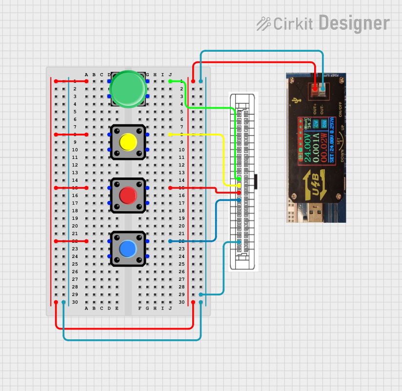
24V Pushbutton Control Interface with 40-Pin Connector

Circuit Documentation
Summary of the Circuit
The circuit in question appears to be a simple control interface utilizing a 24V power supply unit (PSU) and multiple pushbuttons connected to a 40-pin connector. The pushbuttons are likely used to trigger signals through the connector to another system or microcontroller for further processing. The 24V PSU provides the necessary power for the circuit, and the common ground is established through the connector. There is no embedded code provided for any microcontrollers within the circuit, suggesting that the circuit's primary function is to interface with an external controller.
Component List
24V Power Supply Unit (PSU)
- Description: A power supply unit that provides a 24V output.
- Pins:
- 24V +
- 0V
Pushbutton
- Description: A standard pushbutton switch.
- Pins:
- Pin 1 (Normally Open contact)
- Pin 2 (Common contact)
- Pin 3 (Normally Closed contact)
- Pin 4 (Alternate contact)
40 Pin Connector
- Description: A connector with 40 pins used for interfacing with other systems.
- Pins:
- 0V for output pins 5D-20D
- Com for input pins 5c-20C
- No Connection (NC)
- GP In 0-15 (General Purpose Input)
- GP Out 0-15 (General Purpose Output)
- 24V for output pins 5D-20D
Wiring Details
24V Power Supply Unit (PSU)
- 24V +: Connected to the common contact (Pin 2) of all pushbuttons.
- 0V: Connected to the "Com for input pins 5c-20C" on the 40 Pin Connector.
Pushbuttons
- Pushbutton 1:
- Pin 1: Connected to "GP In 9" on the 40 Pin Connector.
- Pin 2: Connected to "24V +" on the 24V PSU.
- Pushbutton 2:
- Pin 1: Connected to "GP In 10" on the 40 Pin Connector.
- Pin 2: Connected to "24V +" on the 24V PSU.
- Pushbutton 3:
- Pin 1: Connected to "GP In 11" on the 40 Pin Connector.
- Pin 2: Connected to "24V +" on the 24V PSU.
- Pushbutton 4:
- Pin 1: Connected to "GP In 12" on the 40 Pin Connector.
- Pin 2: Connected to "24V +" on the 24V PSU.
40 Pin Connector
- Com for input pins 5c-20C: Connected to "0V" on the 24V PSU.
- GP In 9-12: Each connected to "Pin 1" of the corresponding Pushbutton 1-4.
Documented Code
No code has been provided for any microcontrollers within the circuit. If the circuit is intended to interface with an external controller, the code would be expected to reside on that external system. The documentation of the code would include the initialization of the input pins connected to the pushbuttons, debouncing logic, and the handling of button press events to trigger appropriate actions. Since no code is available, this section remains empty.