Arduino Nano-Based Bluetooth Temperature and Humidity Monitor with OLED Display and Alert Buzzer
Circuit Documentation
Summary
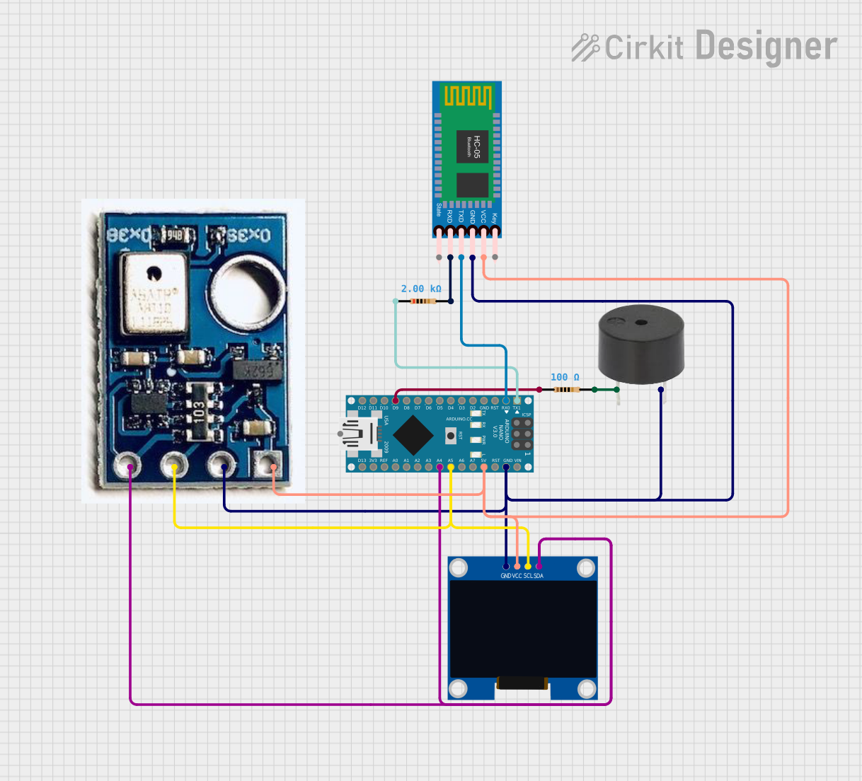
The circuit in question is designed to monitor temperature and humidity using an AHT10 sensor, display the readings on a 128x64 OLED display, and provide a visual alert through a buzzer if the temperature exceeds a predefined threshold. The circuit is controlled by an Arduino Nano microcontroller, which also handles Bluetooth communication through an HC-05 Bluetooth module. The circuit includes resistors for current limiting and pull-up purposes.
Component List
Arduino Nano
- Microcontroller board based on the ATmega328P
- It has a variety of digital and analog I/O pins and supports serial communication.
Buzzer
- An electromechanical component that produces sound when energized.
- Typically used for audible alerts or alarms.
128x64 OLED Display (I2C IIC SPI Serial)
- A small graphical display with organic light-emitting diodes.
- Communicates with the microcontroller via I2C protocol.
Resistor (100 Ohms)
- A passive two-terminal electrical component that implements electrical resistance as a circuit element.
- Used for current limiting or voltage dropping.
Resistor (2000 Ohms)
- Another resistor with a higher resistance value.
- It may be used for pull-up purposes or to limit current to a safe level for other components.
HC-05 Bluetooth Module
- A wireless communication module that allows for Bluetooth connectivity.
- It can be used to send and receive data between the Arduino and a Bluetooth-enabled device.
AHT10
- A high-precision temperature and humidity sensor.
- Provides digital output and communicates over the I2C bus.
Wiring Details
Arduino Nano
D1/TXconnected to a 2000 Ohm resistor.D0/RXconnected toTXDon the HC-05 Bluetooth Module.D9connected to one end of a 100 Ohm resistor, the other end connected to the buzzer.GNDconnected to the ground pins of all other components.5Vsupplies power to the VCC pins of the HC-05 Bluetooth Module, AHT10, and OLED Display.A5connected to theSCLpins of the AHT10 and OLED Display for I2C clock.A4connected to theSDApins of the AHT10 and OLED Display for I2C data.
Buzzer
PINconnected to the other end of the 100 Ohm resistor.GNDconnected to the common ground.
128x64 OLED Display (I2C IIC SPI Serial)
GNDconnected to the common ground.SDAconnected toA4on the Arduino Nano for I2C data.SCLconnected toA5on the Arduino Nano for I2C clock.VCCconnected to the 5V supply from the Arduino Nano.
Resistor (100 Ohms)
- One end connected to
D9on the Arduino Nano. - The other end connected to the
PINof the buzzer.
Resistor (2000 Ohms)
- One end connected to
D1/TXon the Arduino Nano. - The other end connected to
RXDon the HC-05 Bluetooth Module.
HC-05 Bluetooth Module
Keynot connected in this configuration.VCCconnected to the 5V supply from the Arduino Nano.TXDconnected toD0/RXon the Arduino Nano.RXDconnected to the other end of the 2000 Ohm resistor.Statenot connected in this configuration.GNDconnected to the common ground.
AHT10
SDAconnected toA4on the Arduino Nano for I2C data.SCLconnected toA5on the Arduino Nano for I2C clock.GNDconnected to the common ground.VINconnected to the 5V supply from the Arduino Nano.
Documented Code
The code for the Arduino Nano is written in C++ and is intended to be compiled and uploaded using the Arduino IDE. The code is responsible for initializing the AHT10 sensor and OLED display, reading temperature and humidity values, displaying these values on the OLED, and controlling the buzzer based on the temperature threshold. Additionally, it handles serial communication to send sensor readings over Bluetooth.
#include <Wire.h>
#include <AHTxx.h>
#include <Adafruit_SSD1306.h>
#include <Adafruit_GFX.h>

#define OLED_WIDTH 128
#define OLED_HEIGHT 64
#define OLED_ADDR 0x3C
#define BUZZER_PIN 9  // Define the pin for the buzzer
#define TEMP_THRESHOLD 36.0  // Temperature threshold for buzzer

Adafruit_SSD1306 display(OLED_WIDTH, OLED_HEIGHT);
float ahtValue;  // to store T/RH result
AHTxx aht10(AHTXX_ADDRESS_X38, AHT1x_SENSOR);  // sensor address, sensor type

void setup() {
  Serial.begin(115200);  // Serial communication for Bluetooth
  display.begin(SSD1306_SWITCHCAPVCC, OLED_ADDR);
  display.clearDisplay();

  while (aht10.begin() != true) {
    Serial.println(F("AHT1x not connected or fail to load calibration coefficient"));
    delay(5000);
  }

  Serial.println(F("AHT10 OK"));

  pinMode(BUZZER_PIN, OUTPUT); // Set buzzer pin as output
  digitalWrite(BUZZER_PIN, LOW); // Ensure buzzer is off initially
}

void loop() {
  // Read temperature
  ahtValue = aht10.readTemperature();
  display.clearDisplay();
  display.setTextSize(2);
  display.setTextColor(WHITE);
  display.setCursor(30, 0);
  display.println(F("Temp-"));

  if (ahtValue != AHTXX_ERROR) {
    display.setTextSize(2);
    display.setTextColor(WHITE);
    display.setCursor(35, 25);
    display.println(ahtValue);
    display.display();

    // Check if temperature exceeds the threshold of 36°C and control buzzer
    if (ahtValue > TEMP_THRESHOLD) {
      digitalWrite(BUZZER_PIN, HIGH); // Turn on buzzer
    } else {
      digitalWrite(BUZZER_PIN, LOW);  // Turn off buzzer
    }

    // Send temperature over Bluetooth
    Serial.print("Temperature: ");
    Serial.print(ahtValue);
    Serial.println(" C");
  } else {
    printStatus();
    digitalWrite(BUZZER_PIN, LOW); // Turn off buzzer if error occurs
  }

  delay(2000);  // Delay between temperature readings

  // Read humidity
  ahtValue = aht10.readHumidity();
  display.clearDisplay();
  display.setTextSize(2);
  display.setTextColor(WHITE);
  display.setCursor(30, 0);
  display.println(F("Humd-"));

  if (ahtValue != AHTXX_ERROR) {
    display.setTextSize(2);
    display.setTextColor(WHITE);
    display.setCursor(35, 25);
    display.println(ahtValue);
    display.display();

    // Send humidity over Bluetooth
    Serial.print("Humidity: ");
    Serial.print(ahtValue);
    Serial.println(" %");
  } else {
    printStatus();
  }

  delay(2000);  // Delay between humidity readings
}

void printStatus() {
  switch (aht10.getStatus()) {
    case AHTXX_NO_ERROR:
      Serial.println(F("No error"));
      break;
    case AHTXX_BUSY_ERROR:
      Serial.println(F("Sensor busy, increase polling time"));
      break;
    case AHTXX_ACK_ERROR:
      Serial.println(F("Sensor didn't return ACK, check connection"));
      break;
    case AHTXX_DATA_ERROR:
      Serial.println(F("Received data smaller than expected, check connection"));
      break;
    case AHTXX_CRC8_ERROR:
      Serial.println(F("CRC8 error, data may be corrupt"));
      break;
    default:
      Serial.println(F("Unknown status"));
      break;
  }
}
This code includes libraries for the AHTxx sensor and the Adafruit SSD1306 OLED display, defines constants for the display size and I2C address, and sets up the necessary pins and thresholds. The setup() function initializes the serial communication, display, and sensor, while the loop() function continuously reads the sensor data, updates the display, and checks the temperature against the threshold to control the buzzer. It also includes a printStatus() function to output sensor status messages to the serial monitor.