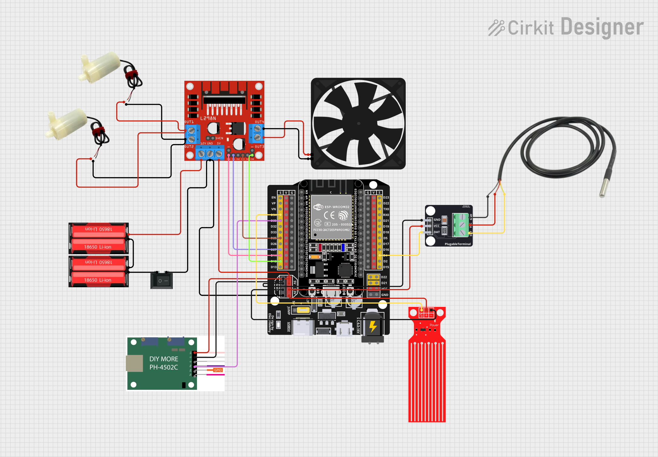
ESP32-Based Automated Water Level Control and Temperature Monitoring System

Circuit Documentation
Summary
The circuit in question appears to be a control system that utilizes an ESP32 microcontroller to interface with various sensors and actuators. The system includes water level and temperature sensors, a pH sensor, two 18650 Li-Ion batteries for power, a motor driver to control water pumps and a fan, and a rocker switch for power control. The ESP32 reads sensor data and controls the actuators accordingly. This could be part of an automated plant watering system or an aquarium control system, where maintaining water levels, temperature, and pH balance is crucial.
Component List
ESP32 - Expansion Board
- Microcontroller board with WiFi and Bluetooth capabilities.
- It has a variety of digital I/O pins and power pins.
Water Level Sensor
- Detects the level of water in a tank or reservoir.
- Outputs a signal that can be read by the ESP32.
5v Mini Water Pump (x2)
- Small pumps used for moving water.
- Operated at 5V.
18650 Li-Ion Battery (x2)
- Rechargeable batteries providing power to the circuit.
- Used in series or parallel to achieve the desired voltage and capacity.
Temperature Sensor
- Measures the temperature of the environment or liquid.
- Interfaces with the ESP32 for temperature monitoring.
Module DS18B20
- A digital temperature sensor that communicates over a one-wire interface.
- Can be used to measure the temperature with high accuracy.
Rocker Switch (SPST)
- A single-pole single-throw switch used to control the power to the circuit.
L298N DC Motor Driver
- A module capable of driving DC motors and stepper motors.
- It receives control signals from the ESP32.
Fan
- A small 5V fan used for cooling or air circulation.
PH4502C
- A pH sensor module used to measure the acidity or alkalinity of a solution.
- Outputs an analog signal to the ESP32.
Wiring Details
ESP32 - Expansion Board
D34connected to Water Level Sensor signal pin.D32connected to pH4502C Po pin.D25,D27connected to L298N DC motor driver IN3 and IN1 respectively.D14,D12connected to L298N DC motor driver ENA and ENB respectively.D4connected to Module DS18B20 DAT pin.5Vconnected to pH4502C VCC, L298N DC motor driver 5V, and Module DS18B20 VCC.3.3Vconnected to Water Level Sensor VCC.Gconnected to pH4502C G1, Module DS18B20 GND, Water Level Sensor GND, and L298N DC motor driver GND (through Rocker Switch).
Water Level Sensor
SIGconnected to ESP32 D34.VCCconnected to ESP32 3.3V.GNDconnected to ESP32 G.
5v Mini Water Pump
Positive pinof both pumps connected to L298N DC motor driver OUT1.Negative pinof both pumps connected to L298N DC motor driver OUT2.
18650 Li-Ion Battery
Positiveof one battery connected to L298N DC motor driver 12V.Negativeof one battery connected toPositiveof the other battery.Negativeof the other battery connected to Rocker Switch.
Temperature Sensor
Temp GND Blackconnected to Module DS18B20 GND.Temp VDD Redconnected to Module DS18B20 VCC.Temp DQ Data Yellowconnected to Module DS18B20 DAT.
Module DS18B20
DATconnected to ESP32 D4.VCCconnected to ESP32 3.3V.GNDconnected to ESP32 G.
Rocker Switch (SPST)
1connected to the negative terminal of the second 18650 Li-Ion battery.2connected to L298N DC motor driver GND and ESP32 G.
L298N DC Motor Driver
IN3,IN1connected to ESP32 D25 and D27 respectively.ENA,ENBconnected to ESP32 D14 and D12 respectively.5Vconnected to ESP32 5V.OUT1,OUT2connected to the positive and negative pins of the 5v mini water pumps respectively.OUT3,OUT4connected to the 5V and GND pins of the Fan.12Vconnected to the positive terminal of one 18650 Li-Ion battery.GNDconnected to Rocker Switch and ESP32 G.
Fan
5Vconnected to L298N DC motor driver OUT3.GNDconnected to L298N DC motor driver OUT4.
PH4502C
VCCconnected to ESP32 5V.G1connected to ESP32 G.Poconnected to ESP32 D32.
Documented Code
No code was provided for the microcontrollers in the circuit. The documentation of the code would typically include a description of the functionality implemented, the setup and loop functions for an Arduino-based microcontroller like the ESP32, and any functions or libraries used to interface with the sensors and actuators. Since no code is available, this section cannot be completed.