
ESP32 and SIM900A IoT Meter with LCD Display and Relay Control
View and Edit Project In Cirkit Designer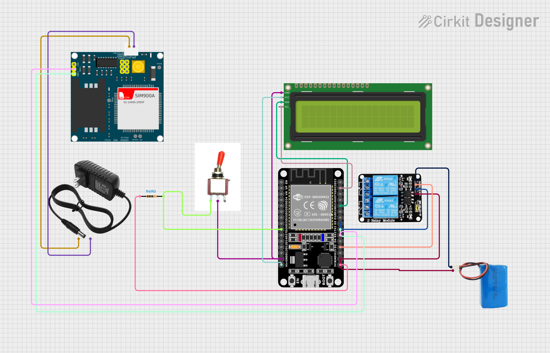
Circuit Documentation
Summary
This document provides a detailed overview of a circuit that includes an ESP32 microcontroller, a toggle switch, a 16x2 I2C LCD, a 5V 2-relay module, a SIM900A GSM module, a 5V battery, a 12V power supply, and a resistor. The circuit is designed to interface these components to create an IoT meter project.
Component List
Toggle Switch
- Description: A simple toggle switch used to control the circuit.
- Pins: Vcc, Sig, Gnd
ESP32 (30 pin)
- Description: A powerful microcontroller with built-in Wi-Fi and Bluetooth capabilities.
- Pins: EN, VP, VN, D34, D35, D32, D33, D25, D26, D27, D14, D12, D13, GND, Vin, D23, D22, TX0, RX0, D21, D19, D18, D5, TX2, RX2, D4, D2, D15, 3V3
Resistor
- Description: A resistor used to limit current in the circuit.
- Pins: pin1, pin2
- Properties: Resistance: NaN Ohms
5V 2-Relay JD-VCC
- Description: A relay module used to control high voltage devices.
- Pins: JD-VCC, VCC, GND, IN1, IN2, NO, COM, NC
5V Battery
- Description: A 5V battery used to power the circuit.
- Pins: positive, negative
16x2 I2C LCD
- Description: A 16x2 character LCD with I2C interface.
- Pins: GND, VCC, SDA, SCL
12V Power Supply
- Description: A 12V power supply used to power the SIM900A module.
- Pins: +, -
SIM900A
- Description: A GSM module used for communication.
- Pins: GND, DB9-3 (RXD), DB9-2 (TXD), 5V, 3VR, 5VR, 3VT, 5VT, VCC, Ring, RESTART, RESET, STATUS
Wiring Details
Toggle Switch
Vcc is connected to:
- Resistor pin2
- ESP32 D26
Sig is connected to:
- 16x2 I2C LCD GND
- ESP32 GND
ESP32 (30 pin)
D26 is connected to:
- Toggle Switch Vcc
- Resistor pin2
GND is connected to:
- Toggle Switch Sig
- 16x2 I2C LCD GND
- 5V 2-Relay JD-VCC GND
- 5V Battery negative
Vin is connected to:
- 16x2 I2C LCD VCC
D22 is connected to:
- 16x2 I2C LCD SCL
D21 is connected to:
- 16x2 I2C LCD SDA
D5 is connected to:
- 5V 2-Relay JD-VCC IN1
TX2 is connected to:
- SIM900A DB9-2 (TXD)
RX2 is connected to:
- SIM900A DB9-3 (RXD)
D2 is connected to:
- 5V 2-Relay JD-VCC IN2
3V3 is connected to:
- Resistor pin1
Resistor
pin2 is connected to:
- Toggle Switch Vcc
- ESP32 D26
pin1 is connected to:
- ESP32 3V3
5V 2-Relay JD-VCC
IN1 is connected to:
- ESP32 D5
IN2 is connected to:
- ESP32 D2
GND is connected to:
- 5V Battery negative
- ESP32 GND
VCC is connected to:
- 5V Battery positive
5V Battery
positive is connected to:
- 5V 2-Relay JD-VCC VCC
negative is connected to:
- 5V 2-Relay JD-VCC GND
- ESP32 GND
16x2 I2C LCD
GND is connected to:
- Toggle Switch Sig
- ESP32 GND
VCC is connected to:
- ESP32 Vin
SCL is connected to:
- ESP32 D22
SDA is connected to:
- ESP32 D21
12V Power Supply
+ is connected to:
- SIM900A 5V
- is connected to:
- SIM900A GND
SIM900A
DB9-2 (TXD) is connected to:
- ESP32 TX2
DB9-3 (RXD) is connected to:
- ESP32 RX2
5V is connected to:
- 12V Power Supply +
GND is connected to:
- 12V Power Supply -
Code Documentation
ESP32 Code
#include <LCD-I2C.h>

LCD_I2C lcd(0x27, 16, 2); // Default address of most PCF8574 modules, change according

void setup() {
    // If you are using more I2C devices using the Wire library use lcd.begin(false)
    // this stop the library(LCD-I2C) from calling Wire.begin()
    lcd.begin();
    lcd.display();
    lcd.backlight();
}

void loop()
{
    lcd.print("IOT METER PROJECT"); // You can make spaces using well... spaces
    lcd.setCursor(5, 1); // Or setting the cursor in the desired position.
    lcd.print(" TEST!");
    delay(500);

    // Flashing the backlight
    for (int i = 0; i < 5; ++i)
    {
        lcd.backlight();
        delay(50);
        lcd.backlightOff();
        delay(50);
    }

    lcd.backlight();
    lcd.clear();
    delay(500);
}
5V 2-Relay JD-VCC Code
void setup() {
  // put your setup code here, to run once:

}

void loop() {
  // put your main code here, to run repeatedly:

}
16x2 I2C LCD Code
void setup() {
  // put your setup code here, to run once:

}

void loop() {
  // put your main code here, to run repeatedly:

}
This documentation provides a comprehensive overview of the circuit, including component descriptions, wiring details, and the code used in the microcontrollers.