
Arduino Nano-Based Traffic Light System with 555 Timer and LDR
View and Edit Project In Cirkit Designer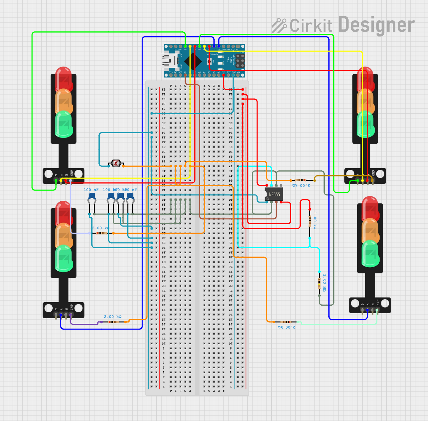
Circuit Documentation
Summary
This circuit is designed to control multiple traffic lights using an Arduino Nano microcontroller and a 555 Timer IC. The circuit includes several resistors, ceramic capacitors, and a photocell (LDR) to manage the timing and control of the traffic lights. The Arduino Nano is programmed to control the traffic lights based on the input from the 555 Timer IC and the photocell.
Component List
Traffic Light
- Pins: Green, Yellow, Red, GND
- Description: Simulates a traffic light with three LEDs (Green, Yellow, Red).
555 Timer IC
- Pins: VCC+, Dis, Th, CV, Rst, Out, Trig, GND
- Description: Used for generating precise time delays and oscillations.
Resistor
- Pins: pin1, pin2
- Description: Limits the current flow in the circuit.
- Properties:
- Resistance: 1000 Ohms
Resistor
- Pins: pin1, pin2
- Description: Limits the current flow in the circuit.
- Properties:
- Resistance: 1000000 Ohms
Resistor
- Pins: pin1, pin2
- Description: Limits the current flow in the circuit.
- Properties:
- Resistance: 2000 Ohms
Ceramic Capacitor
- Pins: pin0, pin1
- Description: Stores electrical energy temporarily.
- Properties:
- Capacitance: 1e-7 Farads
Photocell (LDR)
- Pins: pin 0, pin 1
- Description: Light-dependent resistor used to detect light levels.
Arduino Nano
- Pins: D1/TX, D0/RX, RESET, GND, D2, D3, D4, D5, D6, D7, D8, D9, D10, D11/MOSI, D12/MISO, VIN, 5V, A7, A6, A5, A4, A3, A2, A1, A0, AREF, 3V3, D13/SCK
- Description: Microcontroller used to control the traffic lights.
Wiring Details
Traffic Light 1
- Green: Connected to Arduino Nano pin D6
- Yellow: Connected to Arduino Nano pin D5
- Red: Connected to Arduino Nano pin D4
- GND: Connected to Resistor pin1 (2000 Ohms)
Traffic Light 2
- Green: Connected to Arduino Nano pin D9
- Yellow: Connected to Arduino Nano pin D8
- Red: Connected to Arduino Nano pin D7
- GND: Connected to Resistor pin1 (2000 Ohms)
Traffic Light 3
- Yellow: Connected to Arduino Nano pin D2
- GND: Connected to Resistor pin1 (2000 Ohms)
Traffic Light 4
- Yellow: Connected to Arduino Nano pin D3
- GND: Connected to Resistor pin1 (2000 Ohms)
555 Timer IC
- VCC+: Connected to Resistor pin1 (1000 Ohms)
- Dis: Connected to Resistor pin1 (1000000 Ohms)
- Th: Connected to Ceramic Capacitor pin1
- CV: Not connected
- Rst: Connected to Resistor pin1 (1000 Ohms)
- Out: Connected to Arduino Nano pin A0
- Trig: Connected to Ceramic Capacitor pin1
- GND: Connected to Ceramic Capacitor pin0
Resistor (1000 Ohms)
- pin1: Connected to 555 Timer IC VCC+ and Rst
- pin2: Connected to 555 Timer IC Dis
Resistor (1000000 Ohms)
- pin1: Connected to 555 Timer IC Dis
- pin2: Connected to Ceramic Capacitor pin1
Resistor (2000 Ohms)
- pin1: Connected to Traffic Light GND
- pin2: Connected to Photocell pin1
Ceramic Capacitor
- pin0: Connected to 555 Timer IC GND
- pin1: Connected to 555 Timer IC Th and Trig
Photocell (LDR)
- pin 0: Connected to Ceramic Capacitor pin0
- pin 1: Connected to Resistor pin2 (2000 Ohms)
Arduino Nano
- GND: Connected to Ceramic Capacitor pin0
- 5V: Connected to Resistor pin1 (1000 Ohms)
- D6: Connected to Traffic Light 1 Green
- D5: Connected to Traffic Light 1 Yellow
- D4: Connected to Traffic Light 1 Red
- D9: Connected to Traffic Light 2 Green
- D8: Connected to Traffic Light 2 Yellow
- D7: Connected to Traffic Light 2 Red
- D2: Connected to Traffic Light 3 Yellow
- D3: Connected to Traffic Light 4 Yellow
- A0: Connected to 555 Timer IC Out
Documented Code
Arduino Nano Code (sketch.ino)
void setup() {
  // put your setup code here, to run once:

}

void loop() {
  // put your main code here, to run repeatedly:

}
Documentation (documentation.txt)
This documentation provides a comprehensive overview of the circuit, including a summary, component list, wiring details, and the code used for the Arduino Nano microcontroller.