Arduino Nano and NRF24L01 Wireless Toggle Switch Controller
Circuit Documentation
Summary
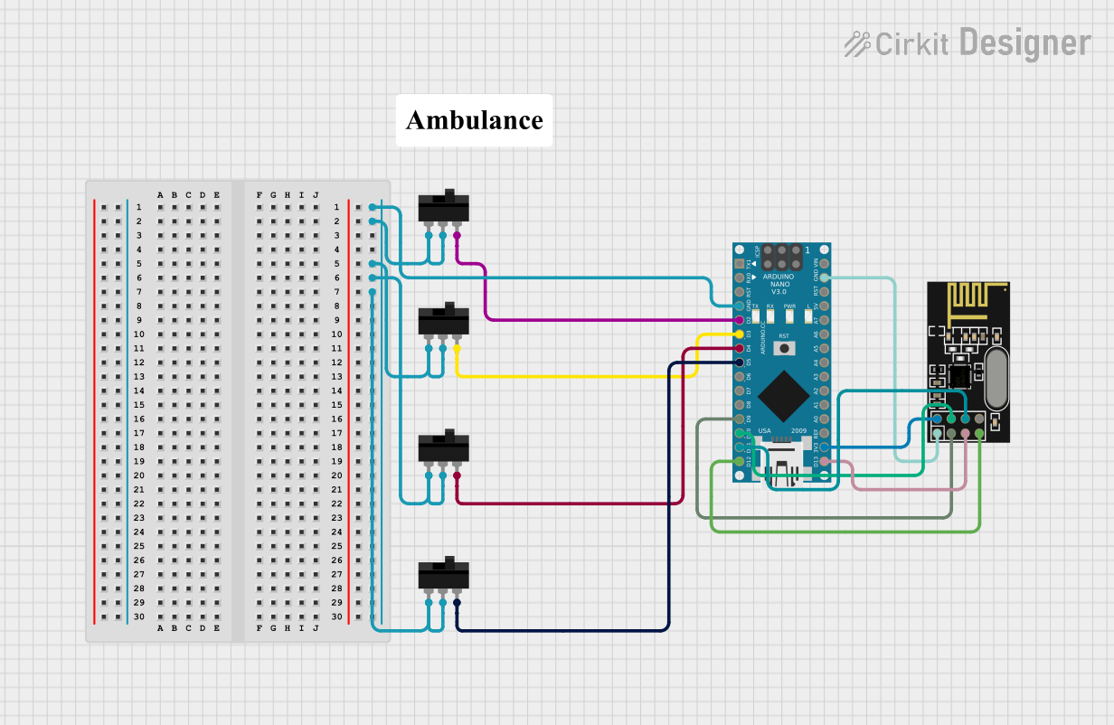
This circuit consists of an Arduino Nano microcontroller, four toggle switches, and an NRF24L01 wireless transceiver module. The Arduino Nano serves as the central control unit, interfacing with the toggle switches and the NRF24L01 module to perform various tasks. The toggle switches are used as input devices, while the NRF24L01 module enables wireless communication.
Component List
Arduino Nano
- Description: A small, complete, and breadboard-friendly board based on the ATmega328P.
- Pins: D1/TX, D0/RX, RESET, GND, D2, D3, D4, D5, D6, D7, D8, D9, D10, D11/MOSI, D12/MISO, VIN, 5V, A7, A6, A5, A4, A3, A2, A1, A0, AREF, 3V3, D13/SCK
- Purpose in Circuit: Central control unit
Toggle Switch (4 instances)
- Description: A simple on/off switch that can be toggled between two states.
- Pins: L1, COM, L2
- Purpose in Circuit: Input device
NRF24L01
- Description: A wireless transceiver module for communication over the 2.4 GHz band.
- Pins: IRQ (not used), MOSI, CSN, VCC (3V), GND, CE, SCK, MISO
- Purpose in Circuit: Wireless communication
Comment
- Description: Placeholder for comments or notes in the circuit.
- Pins: None
- Purpose in Circuit: Documentation
Wiring Details
Arduino Nano
GND is connected to:
- Toggle Switch 1: L1, COM
- Toggle Switch 2: L1, COM
- Toggle Switch 3: L1, COM
- Toggle Switch 4: L1, COM
- NRF24L01: GND
D2 is connected to:
- Toggle Switch 1: L2
D3 is connected to:
- Toggle Switch 2: L2
D4 is connected to:
- Toggle Switch 3: L2
D5 is connected to:
- Toggle Switch 4: L2
D9 is connected to:
- NRF24L01: CE
D10 is connected to:
- NRF24L01: CSN
D11/MOSI is connected to:
- NRF24L01: MOSI
D12/MISO is connected to:
- NRF24L01: MISO
3V3 is connected to:
- NRF24L01: VCC (3V)
D13/SCK is connected to:
- NRF24L01: SCK
Toggle Switch 1
- L1 is connected to:
- Arduino Nano: GND
- COM is connected to:
- Arduino Nano: GND
- L2 is connected to:
- Arduino Nano: D2
Toggle Switch 2
- L1 is connected to:
- Arduino Nano: GND
- COM is connected to:
- Arduino Nano: GND
- L2 is connected to:
- Arduino Nano: D3
Toggle Switch 3
- L1 is connected to:
- Arduino Nano: GND
- COM is connected to:
- Arduino Nano: GND
- L2 is connected to:
- Arduino Nano: D4
Toggle Switch 4
- L1 is connected to:
- Arduino Nano: GND
- COM is connected to:
- Arduino Nano: GND
- L2 is connected to:
- Arduino Nano: D5
NRF24L01
- CE is connected to:
- Arduino Nano: D9
- CSN is connected to:
- Arduino Nano: D10
- MOSI is connected to:
- Arduino Nano: D11/MOSI
- MISO is connected to:
- Arduino Nano: D12/MISO
- GND is connected to:
- Arduino Nano: GND
- VCC (3V) is connected to:
- Arduino Nano: 3V3
- SCK is connected to:
- Arduino Nano: D13/SCK
Documented Code
Arduino Nano Code (sketch.ino)
void setup() {
  // put your setup code here, to run once:

}

void loop() {
  // put your main code here, to run repeatedly:

}
Documentation (documentation.txt)
This documentation provides a comprehensive overview of the circuit, including a summary, detailed component list, wiring details, and the code used in the Arduino Nano.