
Arduino UNO-Based Smart Environmental Monitoring and Control System with Bluetooth Connectivity
View and Edit Project In Cirkit Designer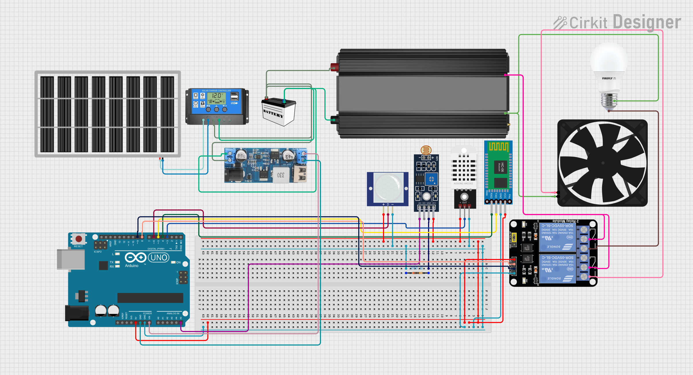
Circuit Documentation
Summary
This circuit integrates various components including an Arduino UNO, Bluetooth HC-06 module, sensors (LDR LM393, DHT22, PIR Motion Sensor), a relay module, power supply components (solar panel, solar charge controller, 12V battery, step-down power converter, power inverter), and output devices (bulb, fan). The Arduino UNO serves as the central microcontroller, interfacing with the Bluetooth module for wireless communication, sensors for environmental data, and a relay module for controlling power to the bulb and fan. The power supply components ensure a stable power source for the circuit, utilizing solar energy stored in a battery, with voltage regulation for the different components.
Component List
- Arduino UNO: A microcontroller board based on the ATmega328P, featuring digital and analog I/O pins.
- Bluetooth HC-06: A wireless communication module that allows for Bluetooth connectivity.
- Sensor LDR LM393: A light-dependent resistor sensor module for detecting light intensity.
- DHT22: A sensor for measuring ambient temperature and humidity.
- Resistor (200 Ohms): A passive two-terminal electrical component that implements electrical resistance.
- PIR Motion Sensor (Wokwi Compatible): A sensor that detects motion via infrared signals.
- Relay Module 2 Channel: An electrically operated switch that allows for controlling high power devices.
- Solar Panel: A panel designed to absorb the sun's rays as a source of energy for generating electricity.
- Solar Charge Controller: A device that controls the charging and discharging of the battery from solar panels.
- 12V Battery (Small Size): A storage device for electrical energy.
- 12v to 5v Step Down Power Converter: A device that steps down voltage from 12V to 5V.
- Power Inverter: A device that converts DC to AC power.
- BULB: An electric light with a wire filament heated until it glows.
- Fan: An electric device that creates airflow.
Wiring Details
Arduino UNO
- GND: Connected to the ground pins of the Bluetooth HC-06, DHT22, PIR Motion Sensor, Resistor, and Relay Module 2 Channel.
- 5V: Powers the Bluetooth HC-06, DHT22, LDR LM393, PIR Motion Sensor, and Relay Module 2 Channel.
- Vin: Receives power from the 5V output of the step-down power converter.
- A5: Connected to the A0 pin of the LDR LM393 sensor.
- D9: Controls IN2 on the Relay Module 2 Channel.
- D8: Controls IN1 on the Relay Module 2 Channel.
- D6: Reads the OUT signal from the PIR Motion Sensor.
- D5: Connected to the TXD pin of the Bluetooth HC-06.
- D4: Connected to the RXD pin of the Bluetooth HC-06.
- D3: Reads the Out signal from the DHT22 sensor.
Bluetooth HC-06
- VCC: Powered by the 5V output from the Arduino UNO.
- GND: Connected to the ground network.
- TXD: Sends data to the D5 pin of the Arduino UNO.
- RXD: Receives data from the D4 pin of the Arduino UNO.
Sensor LDR LM393
- A0: Connected to the A5 pin of the Arduino UNO.
- GND: Connected to the ground network.
- VCC: Powered by the 5V output from the Arduino UNO.
DHT22
- +: Powered by the 5V output from the Arduino UNO.
- Out: Sends data to the D3 pin of the Arduino UNO.
- -: Connected to the ground network.
Resistor (200 Ohms)
- pin1: Connected to the ground network.
- pin2: Connected to the GND pin of the LDR LM393 sensor.
PIR Motion Sensor (Wokwi Compatible)
- VCC: Powered by the 5V output from the Arduino UNO.
- OUT: Sends data to the D6 pin of the Arduino UNO.
- GND: Connected to the ground network.
Relay Module 2 Channel
- VCC: Powered by the 5V output from the Arduino UNO.
- IN1: Controlled by the D8 pin of the Arduino UNO.
- IN2: Controlled by the D9 pin of the Arduino UNO.
- GND: Connected to the ground network.
- COM: Connected to the positive terminal of the Power Inverter.
- NO1: Connected to the positive terminal of the BULB.
- NO2: Connected to the 5V pin of the Fan.
Solar Panel
- vcc: Connected to the Solar Cell + of the Solar Charge Controller.
- gnd: Connected to the Solar Cell - of the Solar Charge Controller.
Solar Charge Controller
- Solar Cell +: Connected to the vcc of the Solar Panel.
- Solar Cell -: Connected to the gnd of the Solar Panel.
- Battery +: Connected to the VCC of the 12V Battery, the + of the Power Inverter, and the VIN+ of the step-down power converter.
- Battery -: Connected to the GND of the 12V Battery, the - of the Power Inverter, and the VIN- of the step-down power converter.
12V Battery (Small Size)
- VCC: Connected to the Battery + of the Solar Charge Controller.
- GND: Connected to the Battery - of the Solar Charge Controller.
12v to 5v Step Down Power Converter
- VIN 9v-36v: Not connected in the provided net list.
- VIN+: Connected to the VCC of the 12V Battery.
- VIN-: Connected to the GND of the 12V Battery.
- USB OUTPUT 5V: Not connected in the provided net list.
- 5v OUTPUT: Powers the Vin pin of the Arduino UNO.
- GND: Connected to the ground network.
Power Inverter
- +: Connected to the Battery + of the Solar Charge Controller and the COM of the Relay Module 2 Channel.
- -: Connected to the Battery - of the Solar Charge Controller and the - of the BULB and Fan.
BULB
- +: Connected to the NO1 of the Relay Module 2 Channel.
- -: Connected to the - of the Power Inverter.
Fan
- 5V: Connected to the NO2 of the Relay Module 2 Channel.
- GND: Connected to the - of the Power Inverter.
Documented Code
Arduino UNO Code (sketch.ino)
void setup() {
  // put your setup code here, to run once:

}

void loop() {
  // put your main code here, to run repeatedly:

}
Note: The provided code is a template and does not include any functional code. It needs to be populated with the logic to control the circuit as per the requirements.