Cirkit Designer
Your all-in-one circuit design IDE
Home /
Project Documentation
Arduino-Based GSM Controlled Smart Irrigation System with LCD Display
Circuit Documentation
Summary
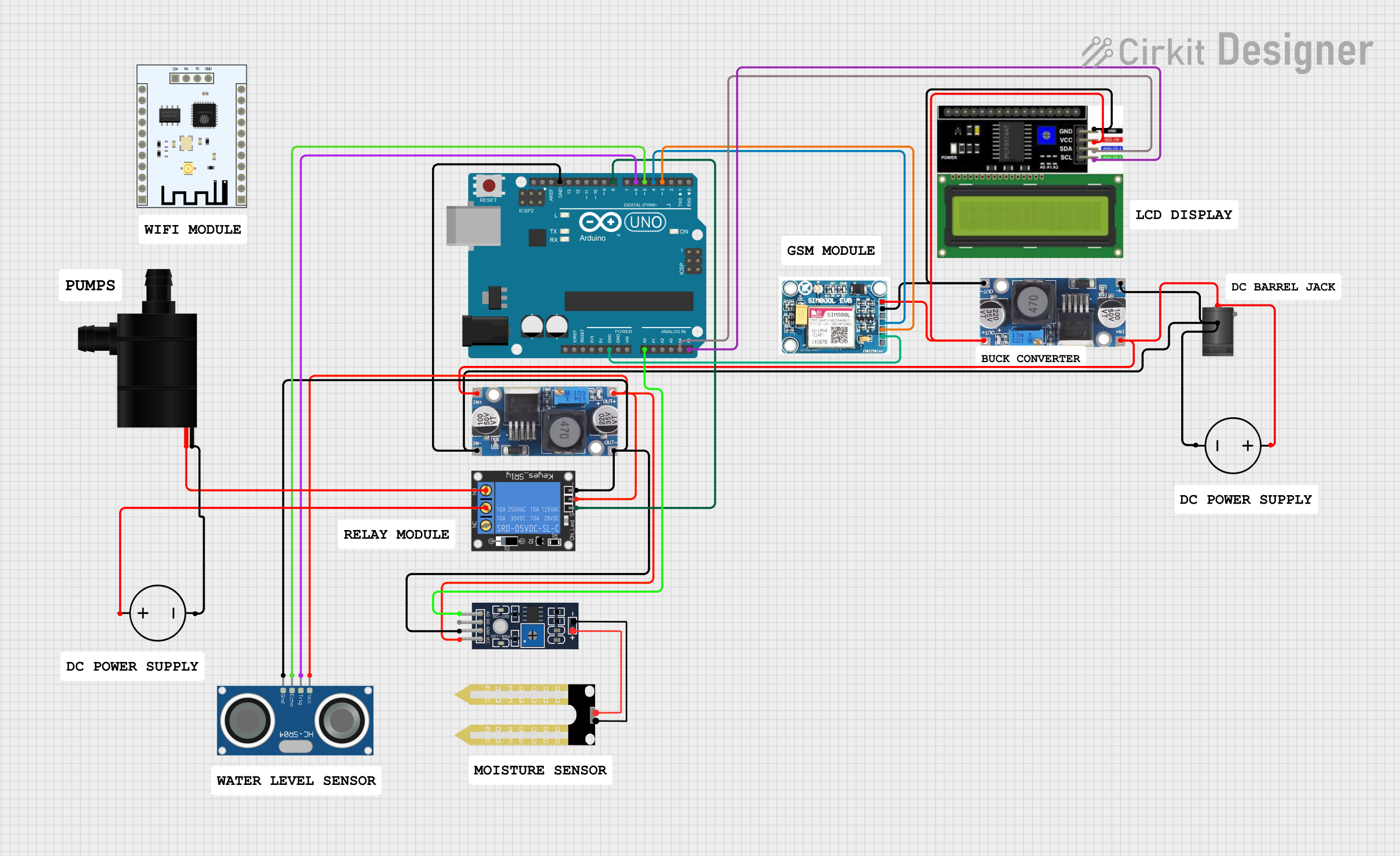
This circuit is a GSM-based irrigation system that monitors soil moisture levels and water tank levels. It uses an Arduino UNO to control a water pump via a relay, and it can send SMS notifications using a SIM 800L GSM module. The system also includes an LCD I2C display for real-time monitoring and an ultrasonic sensor to measure the water tank level.
Component List
2.1mm DC Barrel Jack
- Description: Power input connector
- Pins: switch, sleeve, center
1-Channel Relay (5V 10A)
- Description: Relay module to control the water pump
- Pins: NC, signal, C, power, NO, ground
Humidity YL-69
- Description: Soil moisture sensor
- Pins: A0, D0, GND, VCC
Arduino UNO
- Description: Microcontroller board
- Pins: UNUSED, IOREF, Reset, 3.3V, 5V, GND, Vin, A0, A1, A2, A3, A4, A5, SCL, SDA, AREF, D13, D12, D11, D10, D9, D8, D7, D6, D5, D4, D3, D2, D1, D0
LCD I2C Display
- Description: I2C LCD display for real-time monitoring
- Pins: GND, VCC, SDA, SCL
SIM 800L V2.0 GSM
- Description: GSM module for SMS notifications
- Pins: SIM_TXD, VDD, SIM.RXD, 5V/4V, GND, RST
Step down Buck converter
- Description: Voltage regulator
- Pins: IN +, IN - GND, OUT +, OUT - GND
HC-SR04 Ultrasonic Sensor
- Description: Ultrasonic sensor for measuring water tank level
- Pins: VCC, TRIG, ECHO, GND
Water Pump
- Description: Water pump for irrigation
- Pins: VCC, GND
DC Power Source
- Description: Power supply
- Pins: Ground, Positive
ESP8266 ESP-201 WiFi Module
- Description: WiFi module (not used in this circuit)
- Pins: 3.3V, IO4, D3, D1, D0, CMD, CLK, D2, IO2, IO0, GND, IO5, T_OUT, RST, CHIP_EN, XPD, IO14, IO12, IO13, IO15, RX, TX
Wiring Details
2.1mm DC Barrel Jack
- switch: Connected to GND of the DC Power Source and Step down Buck converters
- center: Connected to Positive of the DC Power Source and Step down Buck converters
1-Channel Relay (5V 10A)
- signal: Connected to D8 of Arduino UNO
- power: Connected to OUT + of Step down Buck converter
- ground: Connected to OUT - GND of Step down Buck converter
- C: Connected to Positive of the DC Power Source
- NO: Connected to VCC of Water Pump
Humidity YL-69
- A0: Connected to A0 of Arduino UNO
- VCC: Connected to OUT + of Step down Buck converter
- GND: Connected to OUT - GND of Step down Buck converter
Arduino UNO
- GND: Connected to GND of SIM 800L GSM, Step down Buck converters, and 2.1mm DC Barrel Jack
- A0: Connected to A0 of Humidity YL-69
- A4: Connected to SDA of LCD I2C Display
- A5: Connected to SCL of LCD I2C Display
- D8: Connected to signal of 1-Channel Relay
- D6: Connected to TRIG of HC-SR04 Ultrasonic Sensor
- D5: Connected to ECHO of HC-SR04 Ultrasonic Sensor
- D4: Connected to SIM_TXD of SIM 800L GSM
- D3: Connected to SIM.RXD of SIM 800L GSM
LCD I2C Display
- GND: Connected to GND of Step down Buck converter
- VCC: Connected to OUT + of Step down Buck converter
- SDA: Connected to A4 of Arduino UNO
- SCL: Connected to A5 of Arduino UNO
SIM 800L V2.0 GSM
- SIM_TXD: Connected to D4 of Arduino UNO
- SIM.RXD: Connected to D3 of Arduino UNO
- 5V/4V: Connected to OUT + of Step down Buck converter
- GND: Connected to GND of Step down Buck converter
Step down Buck converter
- IN +: Connected to Positive of DC Power Source and center of 2.1mm DC Barrel Jack
- IN - GND: Connected to Ground of DC Power Source and switch of 2.1mm DC Barrel Jack
- OUT +: Connected to VCC of Humidity YL-69, power of 1-Channel Relay, VCC of LCD I2C Display, and 5V/4V of SIM 800L GSM
- OUT - GND: Connected to GND of Humidity YL-69, ground of 1-Channel Relay, GND of LCD I2C Display, and GND of SIM 800L GSM
HC-SR04 Ultrasonic Sensor
- TRIG: Connected to D6 of Arduino UNO
- ECHO: Connected to D5 of Arduino UNO
- VCC: Connected to OUT + of Step down Buck converter
- GND: Connected to OUT - GND of Step down Buck converter
Water Pump
- VCC: Connected to NO of 1-Channel Relay
- GND: Connected to Ground of DC Power Source
DC Power Source
- Ground: Connected to GND of Water Pump and Step down Buck converters
- Positive: Connected to C of 1-Channel Relay and Step down Buck converters
Code Documentation
Arduino UNO Code
#include <Wire.h>
#include <LiquidCrystal_I2C.h>
#include <SoftwareSerial.h>

// Pin definitions
const int moistureSensorPin = A0;
const int relayPin = 8;
const int buzzerPin = 10;
const int trigPin = 6;  // Ensure these are connected
const int echoPin = 5;  // Ensure these are connected
const int gsmTxPin = 4;
const int gsmRxPin = 3;

// LCD setup
LiquidCrystal_I2C lcd(0x26, 16, 2);  // Verify the correct address

// GSM setup
SoftwareSerial gsmSerial(gsmTxPin, gsmRxPin);
String incomingSMS;

// Flag to track if a low tank level message has been sent
bool lowTankMessageSent = false;

// Flag to track if a low moisture level message has been sent
bool lowMoistureMessageSent = false;

void beepBuzzer(int duration) {
  digitalWrite(buzzerPin, HIGH);
  delay(duration);
  digitalWrite(buzzerPin, LOW);
}

void waitForGSMNetwork() {
  lcd.init();
  lcd.backlight();
  lcd.setCursor(0, 0);
  lcd.print("Waiting for GSM");
  lcd.setCursor(0, 1);
  lcd.print("network...");

  while (true) {
    gsmSerial.println("AT+CREG?");
    delay(1000);

    if (gsmSerial.available()) {
      String response = gsmSerial.readString();
      if (response.indexOf("+CREG: 0,1") >= 0 || response.indexOf("+CREG: 0,5") >= 0) {
        lcd.init();
        lcd.backlight();
        lcd.setCursor(0, 0);
        lcd.print("GSM Network");
        lcd.setCursor(0, 1);
        lcd.print("Connected");
        delay(2000);
        lcd.clear();
        break;
      }
    }
  }
}

void setup() {
  // Initialize serial communication
  Serial.begin(9600);
  gsmSerial.begin(9600);

  waitForGSMNetwork();

  // Initialize LCD
  lcd.init();
  lcd.backlight();
  lcd.clear();

  // Initialize pins
  pinMode(moistureSensorPin, INPUT);
  pinMode(relayPin, OUTPUT);
  pinMode(buzzerPin, OUTPUT);
  pinMode(trigPin, OUTPUT);
  pinMode(echoPin, INPUT);
  digitalWrite(relayPin, HIGH);

  // Beep buzzer to indicate system start
  beepBuzzer(100);
  delay(100);
  beep