
Arduino Nano-Based Smart Sensor System with RS485 Communication and RGB LED Control
View and Edit Project In Cirkit Designer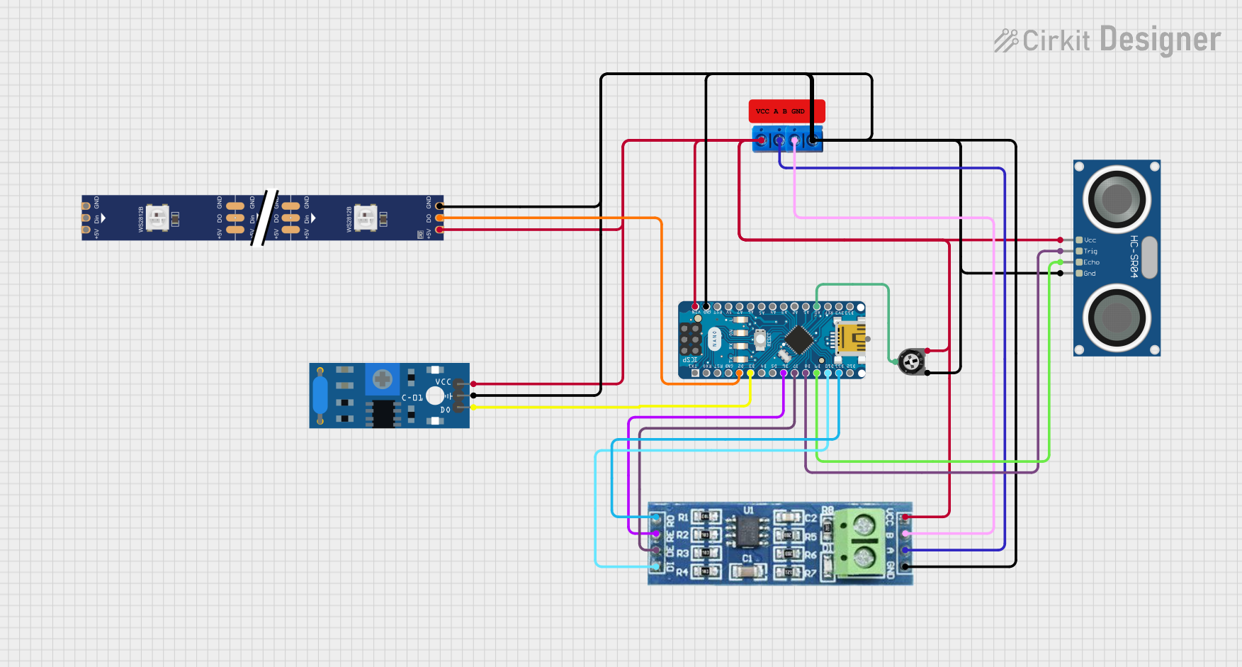
Circuit Documentation
Summary
This circuit integrates an Arduino Nano microcontroller with various sensors and modules, including an RS485 communication module, a SW-420 vibration sensor, a WS2812 RGB LED strip, an HC-SR04 ultrasonic sensor, and a trimmer potentiometer. The circuit is designed to monitor environmental conditions and control outputs based on sensor inputs. The Arduino Nano is programmed to handle these tasks, with the code provided in the final section.
Component List
Arduino Nano
- Description: A compact microcontroller board based on the ATmega328P.
- Pins: D1/TX, D0/RX, RESET, GND, D2, D3, D4, D5, D6, D7, D8, D9, D10, D11/MOSI, D12/MISO, VIN, 5V, A7, A6, A5, A4, A3, A2, A1, A0, AREF, 3V3, D13/SCK
RS485
- Description: A communication module for RS485 serial communication.
- Pins: VCC, RO, RE, GND, B, A, DE, DI
SW-420 Vibration Sensor
- Description: A sensor module to detect vibrations.
- Pins: vcc, Ground, Digital output
WS2812 RGB LED strip
- Description: An addressable RGB LED strip.
- Pins: DIN, 5V, GND, DO
HC-SR04 Ultrasonic Sensor
- Description: A sensor module for measuring distance using ultrasonic waves.
- Pins: VCC, TRIG, ECHO, GND
Terminal PCB 2 Pin
- Description: A terminal block for connecting wires.
- Pins: Pin A, Pin B
Trimmer Potentiometer
- Description: A variable resistor used to adjust voltage.
- Pins: leg1, wiper, leg2
- Properties: Resistance: 10000 Ohms
Wiring Details
Arduino Nano
- D2: Connected to WS2812 RGB LED strip (DO)
- D3: Connected to SW-420 Vibration Sensor (Digital output)
- D6: Connected to RS485 (RE)
- D7: Connected to RS485 (DE)
- D8: Connected to HC-SR04 Ultrasonic Sensor (TRIG)
- D9: Connected to HC-SR04 Ultrasonic Sensor (ECHO)
- D10: Connected to RS485 (DI)
- D11/MOSI: Connected to RS485 (RO)
- VIN: Connected to HC-SR04 Ultrasonic Sensor (VCC), WS2812 RGB LED strip (5V), SW-420 Vibration Sensor (vcc), Terminal PCB 2 Pin (Pin A), Trimmer Potentiometer (leg2), RS485 (VCC)
- GND: Connected to HC-SR04 Ultrasonic Sensor (GND), WS2812 RGB LED strip (GND), SW-420 Vibration Sensor (Ground), Terminal PCB 2 Pin (Pin B), Trimmer Potentiometer (leg1), RS485 (GND)
- A0: Connected to Trimmer Potentiometer (wiper)
RS485
- RE: Connected to Arduino Nano (D6)
- DE: Connected to Arduino Nano (D7)
- DI: Connected to Arduino Nano (D10)
- RO: Connected to Arduino Nano (D11/MOSI)
- VCC: Connected to Arduino Nano (VIN)
- GND: Connected to Arduino Nano (GND)
- B: Connected to Terminal PCB 2 Pin (Pin A)
- A: Connected to Terminal PCB 2 Pin (Pin B)
SW-420 Vibration Sensor
- vcc: Connected to Arduino Nano (VIN)
- Ground: Connected to Arduino Nano (GND)
- Digital output: Connected to Arduino Nano (D3)
WS2812 RGB LED strip
- DIN: Not connected
- 5V: Connected to Arduino Nano (VIN)
- GND: Connected to Arduino Nano (GND)
- DO: Connected to Arduino Nano (D2)
HC-SR04 Ultrasonic Sensor
- VCC: Connected to Arduino Nano (VIN)
- TRIG: Connected to Arduino Nano (D8)
- ECHO: Connected to Arduino Nano (D9)
- GND: Connected to Arduino Nano (GND)
Terminal PCB 2 Pin
- Pin A: Connected to RS485 (B)
- Pin B: Connected to RS485 (A)
Trimmer Potentiometer
- leg1: Connected to Arduino Nano (GND)
- wiper: Connected to Arduino Nano (A0)
- leg2: Connected to Arduino Nano (VIN)
Code Documentation
#include <Wire.h>
#include <RTClib.h>
#include <LiquidCrystal_I2C.h>

// Initialize the LCD display with I2C address 0x27 and size 16x2
LiquidCrystal_I2C lcd(0x27, 16, 2);

// Initialize the RTC module
RTC_DS3231 rtc;

// Variables to store login and logout times
DateTime loggedIn;
DateTime loggedOut;

// Variable to store the period (AM/PM)
String period = "AM";

// Pin definitions
const byte BUZZER_PIN = 5;
const byte BUTTON_PIN = 3;

// Variables to track button state
byte lastState = LOW;  // Previous state of the button
int currentState;      // Current state of the button

void setup() {
  // Start the I2C communication
  Wire.begin();

  // Set pin modes
  pinMode(BUZZER_PIN, OUTPUT);
  pinMode(BUTTON_PIN, INPUT_PULLUP);

  // Initialize serial communication at 9600 bits per second
  Serial.begin(9600);

  // Initialize the LCD display
  lcd.init();
  lcd.backlight();

  // Initialize the RTC module
  if (!rtc.begin()) {
    Serial.print("Couldn't find RTC");
    Serial.flush();
    while (1);
  }

  // Check if the RTC lost power and set the time if necessary
  if (rtc.lostPower()) {
    Serial.println("RTC lost power, let's set the time!");
    rtc.adjust(DateTime(F(__DATE__), F(__TIME__)));
  }

  // Display the login time on the LCD
  lcd.clear();
  lcd.print("Logged In:");
  loggedIn = rtc.now();
  displayTime(loggedIn);
}

void loop() {
  // Read the state of the button
  currentState = digitalRead(BUTTON_PIN);

  // Check for button press (transition from HIGH to LOW)
  if (lastState == HIGH && currentState == LOW) {
    // Sound the buzzer
    tone(BUZZER_PIN, 2000); // Send a 2kHz sound signal
    delay(500);             // for 0.5 seconds
    noTone(BUZZER_PIN);     // Stop the tone

    // Display the logout time on the LCD
    lcd.clear();
    lcd.print("Logged Out:");
    loggedOut = rtc.now();
    displayTime(loggedOut);

    delay(3000);
    lcd.clear();

    // Calculate and display the elapsed time
    long elapsedSeconds = loggedOut.unixtime() - loggedIn.unixtime();
    int elapsedHours = elapsedSeconds / 3600;
    int elapsedMinutes = (elapsedSeconds % 3600) / 60;
    int elapsedSecondsRemaining = elapsedSeconds % 60;

    lcd.print("Elapsed time:");
    lcd.setCursor(0, 1);
    lcd.print(elapsedHours);
    lcd.print("h ");
    lcd.print(elapsedMinutes);
    lcd.print("m ");
    lcd.print(elapsedSecondsRemaining);
    lcd.print("s");

    delay(5000);
    lcd.clear();
  }

  // Update the last state of the button
  lastState = currentState;
}

// Function to display time on the LCD
void displayTime(DateTime time) {
  lcd.setCursor(0, 1);
  int hour = time.hour();
  if (hour >= 12) {
    period = "PM";
    if (hour > 12) {
      hour -= 12;
    }
  } else if (hour == 0) {
    hour = 12;
  }
  lcd.print(hour);
  lcd.print(':');
  if (time.minute() < 10) lcd.print('0'); // Leading zero for minutes
  lcd.print(time.minute());
  lcd.print(':');
  if (time.second() < 10) lcd.print('0'); // Leading zero for seconds
  lcd.print(time.second());
  lcd.print(' ');
  lcd.print(period);
}
This code initializes the LCD display and RTC module, tracks login and logout times, and displays the elapsed time on the LCD. The buzzer sounds when the button is pressed, and the time is displayed in a 12-hour format with AM/PM indication.