
Arduino 101-Based Smart Medicine Dispenser with RFID and LCD Display
View and Edit Project In Cirkit Designer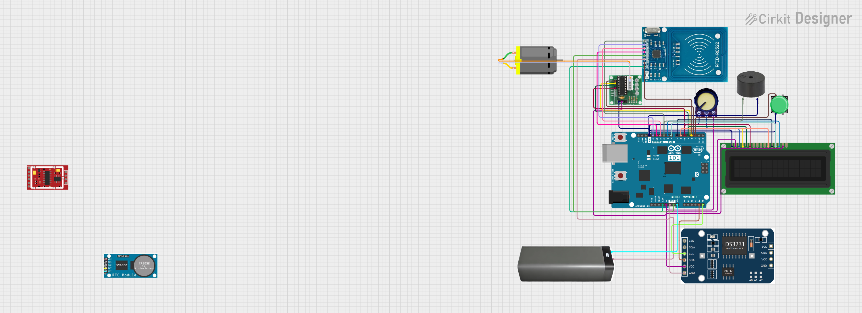
Circuit Documentation
Summary
This document provides a detailed overview of a circuit that includes an Arduino 101 microcontroller, a buzzer, an LCD display, an RFID reader, a real-time clock (RTC) module, a potentiometer, a pushbutton, a DC motor, and a ULN 2003 driver. The circuit is designed to read RFID tags, display information on an LCD, control a motor, and sound a buzzer based on specific conditions. The Arduino 101 is the central controller, interfacing with all other components.
Component List
Arduino 101
- Description: Microcontroller board based on the Intel Curie module.
- Pins: A5/SCL, A4/SDA, AREF, GND, D13/SCK, D12/MISO, D11 PWM/MOSI, D10 PWM/SS, D9 PWM, D8, D7, D6 PWM, D5 PWM, D4, D3 PWM, D2, D1/TX, D0/RX, AIN, ioref, RESET, 3V3, 5V, VIN, A0, A1, A2, A3, ICSP MISO, ICSP SCK, ICSP MOSI
Buzzer
- Description: An audio signaling device.
- Pins: PIN, GND
LCD Display (16 pin)
- Description: 16x2 character LCD display.
- Pins: VSS, VDD, VO, RS, R_W, E, DB0, DB1, DB2, DB3, DB4, DB5, DB6, DB7, A, K
RFID-RC522
- Description: RFID reader module.
- Pins: VCC (3.3V), RST, GND, IRQ, MISO, MOSI, SCK, SDA
RTC Module
- Description: Real-time clock module.
- Pins: 32k, SQW, SCL, SDA, VCC, GND
Potentiometer
- Description: Variable resistor.
- Pins: GND, Output, VCC
Pushbutton
- Description: Momentary pushbutton switch.
- Pins: Pin 2, Pin 1, Pin 3, Pin 4
DC Motor
- Description: Direct current motor.
- Pins: pin 1, pin 2
ULN 2003
- Description: High voltage, high current Darlington transistor array.
- Pins: IN1, IN2, IN3, IN4, IN5, IN6, IN7, GND, +, COIL1, COIL2, COIL3, COIL4, COIL5
Battery Pack
- Description: Power supply.
- Pins: +, -
Wiring Details
Arduino 101
- D10 PWM/SS connected to Buzzer PIN and RFID-RC522 SDA
- GND connected to Pushbutton Pin 2, Buzzer GND, LCD Display VSS, ULN 2003 GND, Potentiometer GND, Battery Pack -, RTC Module GND, RFID-RC522 GND, and RFID-RC522 IRQ
- A5/SCL connected to RTC Module SCL
- D13/SCK connected to RFID-RC522 SCK
- D12/MISO connected to RFID-RC522 MISO
- D11 PWM/MOSI connected to RFID-RC522 MOSI
- D9 PWM connected to LCD Display DB7
- D8 connected to LCD Display DB6
- D7 connected to LCD Display DB5
- D6 PWM connected to LCD Display DB4
- D5 PWM connected to LCD Display E and ULN 2003 IN4
- D4 connected to LCD Display R_W and ULN 2003 IN3
- D3 PWM connected to LCD Display RS and ULN 2003 IN2
- D2 connected to Pushbutton Pin 1, ULN 2003 IN1, and RFID-RC522 RST
- 3V3 connected to RFID-RC522 VCC (3.3V)
- 5V connected to LCD Display VDD, LCD Display A, ULN 2003 +, RTC Module VCC, and Potentiometer VCC
- VIN connected to Battery Pack +
- A4/SDA connected to RTC Module SDA
Buzzer
- PIN connected to Arduino 101 D10 PWM/SS
- GND connected to Arduino 101 GND
LCD Display (16 pin)
- VSS connected to Arduino 101 GND
- VDD connected to Arduino 101 5V
- VO connected to Potentiometer Output
- RS connected to Arduino 101 D3 PWM
- R_W connected to Arduino 101 D4
- E connected to Arduino 101 D5 PWM
- DB4 connected to Arduino 101 D6 PWM
- DB5 connected to Arduino 101 D7
- DB6 connected to Arduino 101 D8
- DB7 connected to Arduino 101 D9 PWM
- A connected to Arduino 101 5V
- K not connected
RFID-RC522
- VCC (3.3V) connected to Arduino 101 3V3
- RST connected to Arduino 101 D2
- GND connected to Arduino 101 GND
- IRQ connected to Arduino 101 GND
- MISO connected to Arduino 101 D12/MISO
- MOSI connected to Arduino 101 D11 PWM/MOSI
- SCK connected to Arduino 101 D13/SCK
- SDA connected to Arduino 101 D10 PWM/SS
RTC Module
- SCL connected to Arduino 101 A5/SCL
- SDA connected to Arduino 101 A4/SDA
- VCC connected to Arduino 101 5V
- GND connected to Arduino 101 GND
Potentiometer
- GND connected to Arduino 101 GND
- Output connected to LCD Display VO
- VCC connected to Arduino 101 5V
Pushbutton
- Pin 2 connected to Arduino 101 GND
- Pin 1 connected to Arduino 101 D2
DC Motor
- pin 1 connected to ULN 2003 COIL1
- pin 2 connected to ULN 2003 COIL2
ULN 2003
- IN1 connected to Arduino 101 D2
- IN2 connected to Arduino 101 D3 PWM
- IN3 connected to Arduino 101 D4
- IN4 connected to Arduino 101 D5 PWM
- GND connected to Arduino 101 GND
- + connected to Arduino 101 5V
- COIL1 connected to DC Motor pin 1
- COIL2 connected to DC Motor pin 2
Battery Pack
- + connected to Arduino 101 VIN
- - connected to Arduino 101 GND
Code Documentation
#include <Wire.h>
#include <LiquidCrystal.h>
#include <SPI.h>
#include <MFRC522.h>
#include <RTClib.h>

#define BUZZER_PIN 10
#define RFID_SS_PIN 10
#define RFID_RST_PIN 2
#define MOTOR_PIN 11
#define BUTTON_PIN 2

LiquidCrystal lcd(3, 4, 5, 6, 7, 8, 9);
MFRC522 rfid(RFID_SS_PIN, RFID_RST_PIN);
RTC_DS3231 rtc;

void setup() {
  Serial.begin(9600);
  while (!Serial);
  lcd.begin(16, 2);
  lcd.print("Initializing...");
  pinMode(BUZZER_PIN, OUTPUT);
  digitalWrite(BUZZER_PIN, LOW);
  pinMode(MOTOR_PIN, OUTPUT);
  digitalWrite(MOTOR_PIN, LOW);
  pinMode(BUTTON_PIN, INPUT_PULLUP);
  SPI.begin();
  rfid.PCD_Init();
  if (!rtc.begin()) {
    lcd.clear();
    lcd.print("RTC not found!");
    while (1);
  }
  if (rtc.lostPower()) {
    rtc.adjust(DateTime(F(__DATE__), F(__TIME__)));
  }
  lcd.clear();
  lcd.print("