Arduino Nano Dual Stepper Motor Controller with A4988 Drivers and Boost Converter
Circuit Documentation
Summary
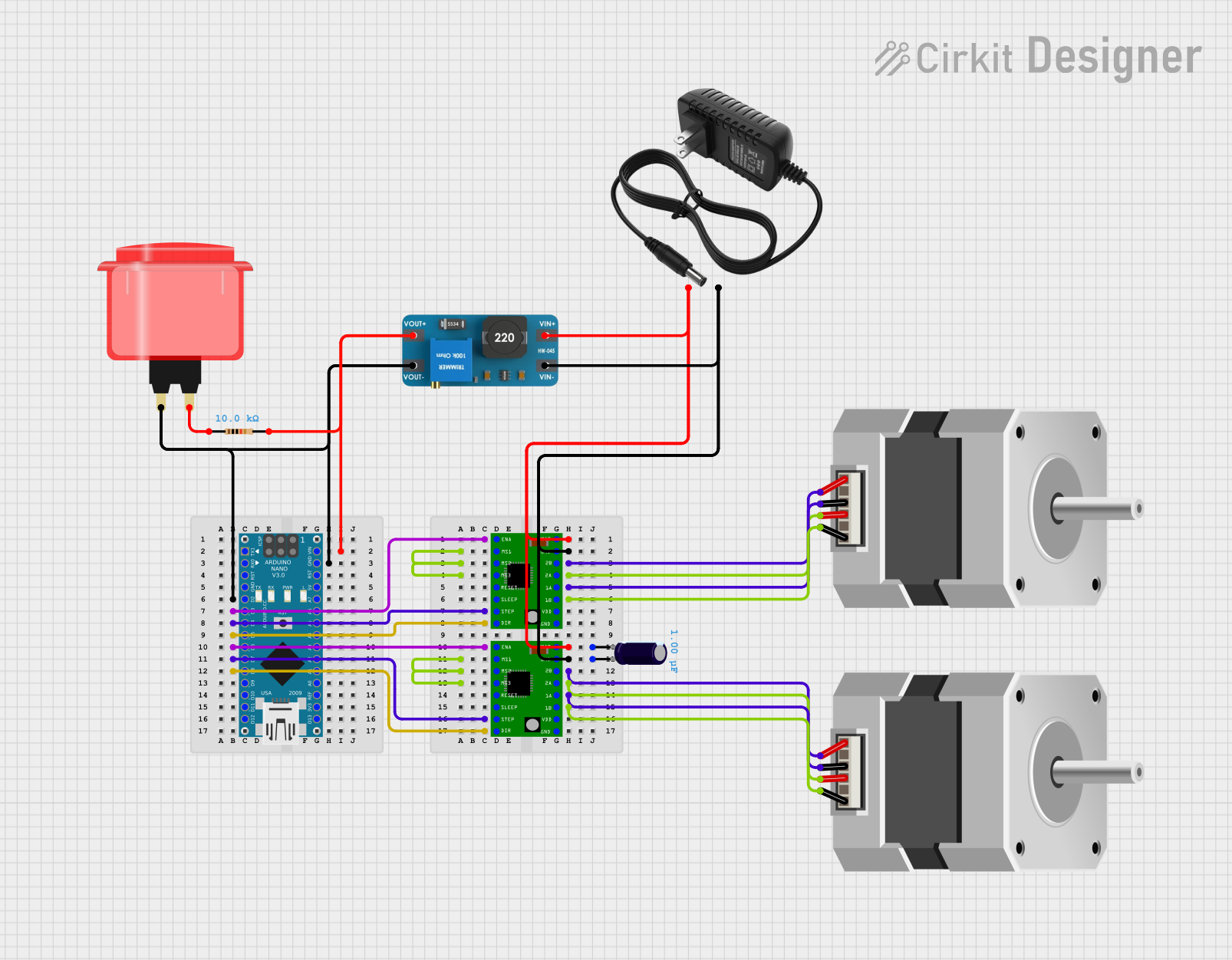
This circuit is designed to control two stepper motors using A4988 stepper motor drivers, an Arduino Nano, and a boost converter. An arcade button is used to enable or disable the motors. The boost converter provides the necessary voltage to the motor drivers. The Arduino Nano controls the direction and step pins for each motor driver.
Component List
A4988 Stepper Motor Driver Carrier
- Pins: ENABLE, MS1, MS2, MS3, RESET, SLEEP, STEP, DIR, GND, VCC, 1B, 1A, 2A, 2B, VMOT
- Description: Stepper motor driver for controlling bipolar stepper motors.
Electrolytic Capacitor
- Pins: -, +
- Description: Capacitor used for filtering.
- Properties:
- Capacitance: 0.000001 Farads
Resistor
- Pins: pin1, pin2
- Description: Resistor used for current limiting.
- Properties:
- Resistance: 10000 Ohms
Stepper Motor (Bipolar)
- Pins: D, B, C, A
- Description: Bipolar stepper motor.
Boost Converter MT3608
- Pins: OUTPUT +, OUTPUT -, INPUT +, INPUT -
- Description: Boost converter for voltage regulation.
Arcade Button (red)
- Pins: no name yet
- Description: Button used for user input.
12V Power Supply
- Pins: +, -
- Description: Power supply providing 12V.
Arduino Nano
- Pins: D1/TX, D0/RX, RESET, GND, D2, D3, D4, D5, D6, D7, D8, D9, D10, D11/MOSI, D12/MISO, VIN, 5V, A7, A6, A5, A4, A3, A2, A1, A0, AREF, 3V3, D13/SCK
- Description: Microcontroller for controlling the circuit.
Wiring Details
A4988 Stepper Motor Driver Carrier
- ENABLE: Connected to Arduino Nano D3
- STEP: Connected to Arduino Nano D4
- DIR: Connected to Arduino Nano D5
- VMOT: Connected to 12V Power Supply +, Boost Converter MT3608 INPUT +
- GND: Connected to 12V Power Supply -, Boost Converter MT3608 INPUT -
- 2B: Connected to Stepper Motor (Bipolar) A
- 2A: Connected to Stepper Motor (Bipolar) B
- 1A: Connected to Stepper Motor (Bipolar) C
- 1B: Connected to Stepper Motor (Bipolar) D
- MS1, MS2, MS3: Internally connected
A4988 Stepper Motor Driver Carrier
- ENABLE: Connected to Arduino Nano D6
- STEP: Connected to Arduino Nano D7
- DIR: Connected to Arduino Nano D8
- VMOT: Connected to 12V Power Supply +, Boost Converter MT3608 INPUT +
- GND: Connected to 12V Power Supply -, Boost Converter MT3608 INPUT -
- 2B: Connected to Stepper Motor (Bipolar) A
- 2A: Connected to Stepper Motor (Bipolar) B
- 1A: Connected to Stepper Motor (Bipolar) C
- 1B: Connected to Stepper Motor (Bipolar) D
- MS1, MS2, MS3: Internally connected
Electrolytic Capacitor
- -: Connected to 12V Power Supply +
- +: Connected to 12V Power Supply -
Resistor
- pin1: Connected to Arcade Button (red)
- pin2: Connected to Arduino Nano VIN, Boost Converter MT3608 OUTPUT +
Stepper Motor (Bipolar)
- A: Connected to A4988 Stepper Motor Driver Carrier 2B
- B: Connected to A4988 Stepper Motor Driver Carrier 2A
- C: Connected to A4988 Stepper Motor Driver Carrier 1A
- D: Connected to A4988 Stepper Motor Driver Carrier 1B
Stepper Motor (Bipolar)
- A: Connected to A4988 Stepper Motor Driver Carrier 2B
- B: Connected to A4988 Stepper Motor Driver Carrier 2A
- C: Connected to A4988 Stepper Motor Driver Carrier 1A
- D: Connected to A4988 Stepper Motor Driver Carrier 1B
Boost Converter MT3608
- OUTPUT +: Connected to Arduino Nano VIN, Resistor pin2
- OUTPUT -: Connected to Arduino Nano GND, Arcade Button (red)
- INPUT +: Connected to 12V Power Supply +
- INPUT -: Connected to 12V Power Supply -
Arcade Button (red)
- no name yet: Connected to Arduino Nano D2, Resistor pin1, Boost Converter MT3608 OUTPUT -
12V Power Supply
- +: Connected to A4988 Stepper Motor Driver Carrier VMOT, Boost Converter MT3608 INPUT +
- -: Connected to A4988 Stepper Motor Driver Carrier GND, Boost Converter MT3608 INPUT -
Arduino Nano
- VIN: Connected to Resistor pin2, Boost Converter MT3608 OUTPUT +
- D2: Connected to Arcade Button (red)
- D3: Connected to A4988 Stepper Motor Driver Carrier ENABLE
- D4: Connected to A4988 Stepper Motor Driver Carrier STEP
- D5: Connected to A4988 Stepper Motor Driver Carrier DIR
- D6: Connected to A4988 Stepper Motor Driver Carrier ENABLE
- D7: Connected to A4988 Stepper Motor Driver Carrier STEP
- D8: Connected to A4988 Stepper Motor Driver Carrier DIR
- GND: Connected to Boost Converter MT3608 OUTPUT -
Code Documentation
/*
 * Arduino-Controlled Dual Stepper Motor Driver with Boost Converter and User Input
 * This code controls two A4988 stepper motor drivers using an Arduino Nano. The
 * direction and step pins for each driver are controlled by the Arduino. An
 * arcade button is used to enable or disable the motors. The boost converter
 * provides the necessary voltage to the motor drivers.
 */

// Pin definitions
const int enablePin1 = 3;
const int stepPin1 = 4;
const int dirPin1 = 5;
const int enablePin2 = 6;
const int stepPin2 = 7;
const int dirPin2 = 8;
const int buttonPin = 2;

// Variables
bool motorsEnabled = false;

void setup() {
  // Initialize pins
  pinMode(enablePin1, OUTPUT);
  pinMode(stepPin1, OUTPUT);
  pinMode(dirPin1, OUTPUT);
  pinMode(enablePin2, OUTPUT);
  pinMode(stepPin2, OUTPUT);
  pinMode(dirPin2, OUTPUT);
  pinMode(buttonPin, INPUT_PULLUP);

  // Disable motors initially
  digitalWrite(enablePin1, HIGH);
  digitalWrite(enablePin2, HIGH);
}

void loop() {
  // Check button state
  if (digitalRead(buttonPin) == LOW) {
    motorsEnabled = !motorsEnabled;
    delay(200); // Debounce delay
  }

  // Enable or disable motors
  if (motorsEnabled) {
    digitalWrite(enablePin1, LOW);
    digitalWrite(enablePin2, LOW);
    // Example motor control
    digitalWrite(dirPin1, HIGH);
    digitalWrite(dirPin2, LOW);
    digitalWrite(stepPin1, HIGH);
    digitalWrite(stepPin2, HIGH);
    delay(1);
    digitalWrite(stepPin1, LOW);
    digitalWrite(stepPin2, LOW);
    delay(1);
  } else {
    digitalWrite(enablePin1, HIGH);
    digitalWrite(enablePin2, HIGH);
  }
}
This code initializes the pins for the stepper motor drivers and the arcade button. It then enters a loop where it checks the state of the button. If the button is pressed, it toggles the state of the motors (enabled or disabled). When the motors are enabled, it sends step and direction signals to the motor drivers.